Non-contact type high-power energy transmission system and application

A non-contact, energy transmission technology, applied in electromagnetic wave systems, electrical components, circuit devices, etc., can solve problems such as power loss, high standby power consumption, system resonance frequency changes, etc., to avoid personal injury and improve energy utilization rate effect

Active Publication Date: 2011-08-17
QINGDAO LU YU ENERGY TECH CO LTD
View PDF3 Cites 41 Cited by
  • Summary
  • Abstract
  • Description
  • Claims
  • Application Information

AI Technical Summary

Problems solved by technology

[0005] 1. When the device parameters of the system drift or are disturbed, or when the load changes (such as when a load among multiple loads is added or removed), these will cause the resonant frequency of the system to change, resulting in switching devices The switching frequency of the system deviates from the resonant frequency of the system, and the energy transferred from the primary side to the secondary side decreases rapidly;
[0006] 2. Because there is a certain delay in the turn-on and turn-off of the switching device, it is difficult for the switching device controlled by soft switching to turn off when the resonant voltage is zero and turn on when the resona

Method used


Image

  • Non-contact type high-power energy transmission system and application
  • Non-contact type high-power energy transmission system and application
  • Non-contact type high-power energy transmission system and application

Examples


Embodiment Construction

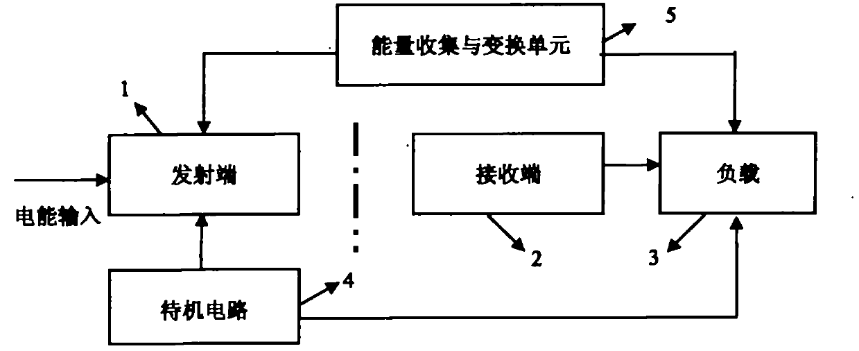
[0037] figure 1 It is a block diagram of the non-contact energy transmission system of the present invention, including five parts including a transmitter 1 , a receiver 2 , a load 3 , a standby circuit 4 , and an energy collection and conversion unit 5 . The transmitting end 1 generates a high-frequency current and provides it to the load power supply of the secondary loop through space magnetic field coupling. The standby circuit 4 controls the input of the power supply of the main circuit through the relay, and can detect whether the load exists in real time, and automatically start or shut down the power supply of the main circuit accordingly. The energy collection and conversion unit 5 collects, converts or heats the energy generated in the system to the primary side or the secondary side, so that the lost energy can be reused and energy loss is reduced.

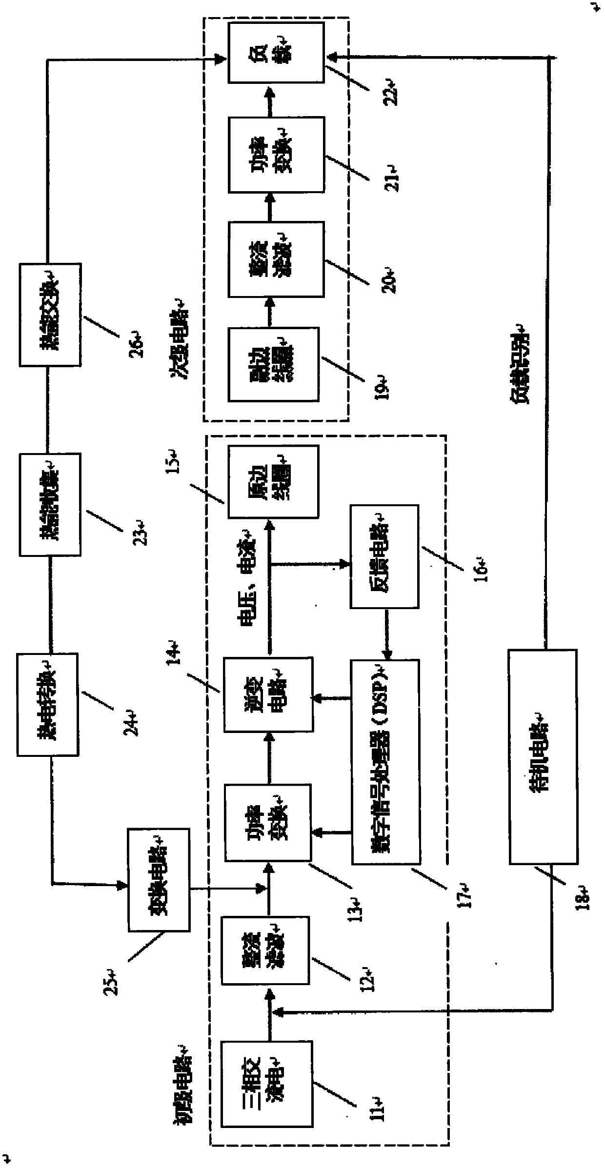
[0038] figure 2 Composition structure diagram for the contactless energy transfer system. The transmitting end in...


PUM


Abstract

The invention discloses a non-contact type high-power energy transmission system which comprises a transmitting end, a receiving end, a load, a standby circuit, an energy collecting and converting unit, and the like, wherein a feedback circuit adjusts the switching frequency of a switching tube by detecting the change of original edge resonant coil current and resonant frequency so that the switching frequency is consistent with the resonant frequency of the system; and by carrying out proper phase compensation on the drive voltage of the switching tube, the circulation generated in an inverting circuit and caused by switching-off delay of the switching tube can be eliminated. The standby circuit can completely eliminate the power supply of a main circuit by a relay. When the load is removed, the circuit can automatically enter a standby state. When the load is charged, the standby circuit can wirelessly detect the existence of the load and automatically start the main circuit to enter a working state. A heat energy collecting and converting system converts heat energy generated in the converting circuit and a switching circuit into available electric energy by thermoelectric materials and feeds back the electric energy to the power input of the main circuit again and realizes the recycling of energy.

Description

technical field [0001] The invention relates to a non-contact high-power energy transmission system and an application device. The efficiency and stability of the system can meet the requirements of practical application. Background technique [0002] At present, electrical equipment used in industrial production usually adopts a contact method and is directly connected to the grid through a plug. This power transmission mode is prone to contact sparks. In some special environments (such as factories, mines, production workshops, etc. containing flammable and explosive gases), the existence of contact sparks may bring major disasters to production activities. In addition, in applications such as marine ships, contact-type electrical contacts are also prone to short-circuit faults due to moisture and other conditions, which greatly reduces the stability and reliability of equipment work. [0003] For non-contact energy transmission systems, electromagnetic induction is usual...

Claims


Application Information

Patent Timeline
IPC IPC(8): H02J17/00H02J50/12
Inventor 韩丽
Owner QINGDAO LU YU ENERGY TECH CO LTD
Why Eureka
Try Eureka