Electrolytic foil and producing method thereof

A technology of electrolytic copper foil and electrolyte, applied in electrolytic process, electroforming, etc., can solve the problems of increased process and ineffective use of tin plating layer, etc., and achieve the effect of high industrial applicability

Active Publication Date: 2011-08-31
FUKUKA METAL FOIL & POWDER CO LTD
View PDF10 Cites 24 Cited by
  • Summary
  • Abstract
  • Description
  • Claims
  • Application Information

AI Technical Summary

Problems solved by technology

[0024] However, from the viewpoint of producing electrolytic copper foil, it is not preferable to apply nickel-plating of the internal diffusion barrier layer because it increases the number of steps, and when forming the above-mentioned flying lead portion, as tin-plating pretreatment, Soft etching is performed on both surfaces of the surf

Method used


Image

  • Electrolytic foil and producing method thereof
  • Electrolytic foil and producing method thereof
  • Electrolytic foil and producing method thereof

Examples


Embodiment 1

[0060] Prepared by 100g / L of sulfuric acid (H 2 SO 4 ) and 280g / L copper sulfate pentahydrate (CuSO 4 ·5H 2 O) formed sulfuric acid-copper sulfate aqueous solution (hereinafter referred to as the electrolyte solution "basic electrolyte solution").

[0061] As additives, polyglycerin (trade name: polyglycerol; product code: PGL-X; manufactured by Daicel Chemical Industry Co., Ltd.), 3-mercapto-1-propanesulfonate sodium, N,N-diethylthiourea (commercial Name: Sansera-EUR; manufactured by Sanshin Chemical Industry) and hydrochloric acid were added to the basic electrolyte solution, and relative to the basic electrolyte solution, the concentration was adjusted so that polyglycerin was 30 mg / L, and sodium 3-mercapto-1-propanesulfonate was 5 mg / L, 1.5 mg / L of N,N-diethylthiourea, and 35 mg / L of chloride ion (see Table 1 described later).

[0062] The electrolytic solution containing the above-mentioned additives is supplied between the insoluble anode made of titanium (coated wit...

Embodiment 2~5、 comparative example 1~4

[0086] In addition to changing the type of additive and the concentration relative to the basic electrolyte, the electrolytic current density, and the temperature of the electrolyte to the data shown in Table 1 described later, the thickness of 18 μm was obtained under the same conditions as in Example 1. Electrolytic copper foil. And each evaluation test was performed similarly to Example 1 about the obtained unprocessed electrolytic copper foil. The results are shown in Table 2 and Table 3 described later.

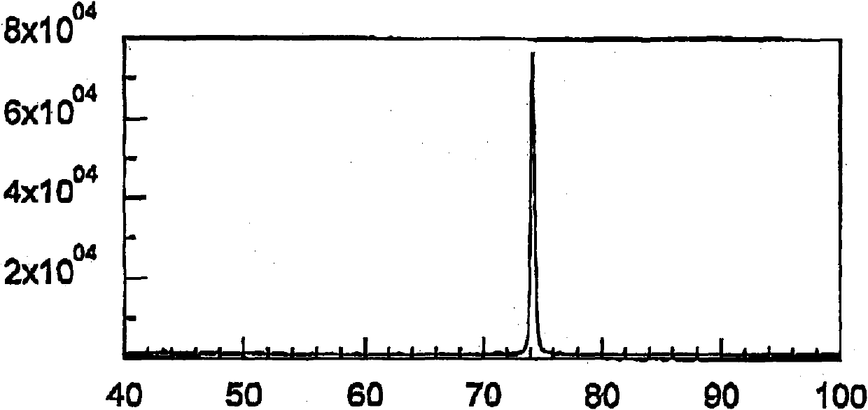
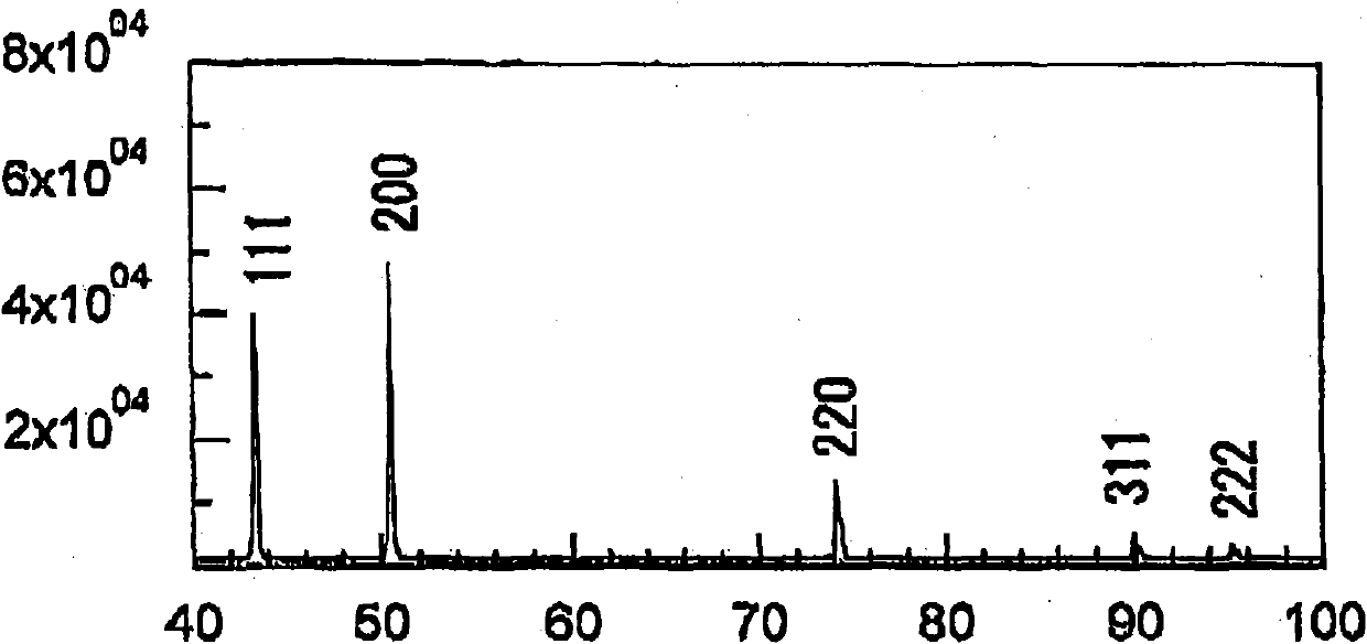
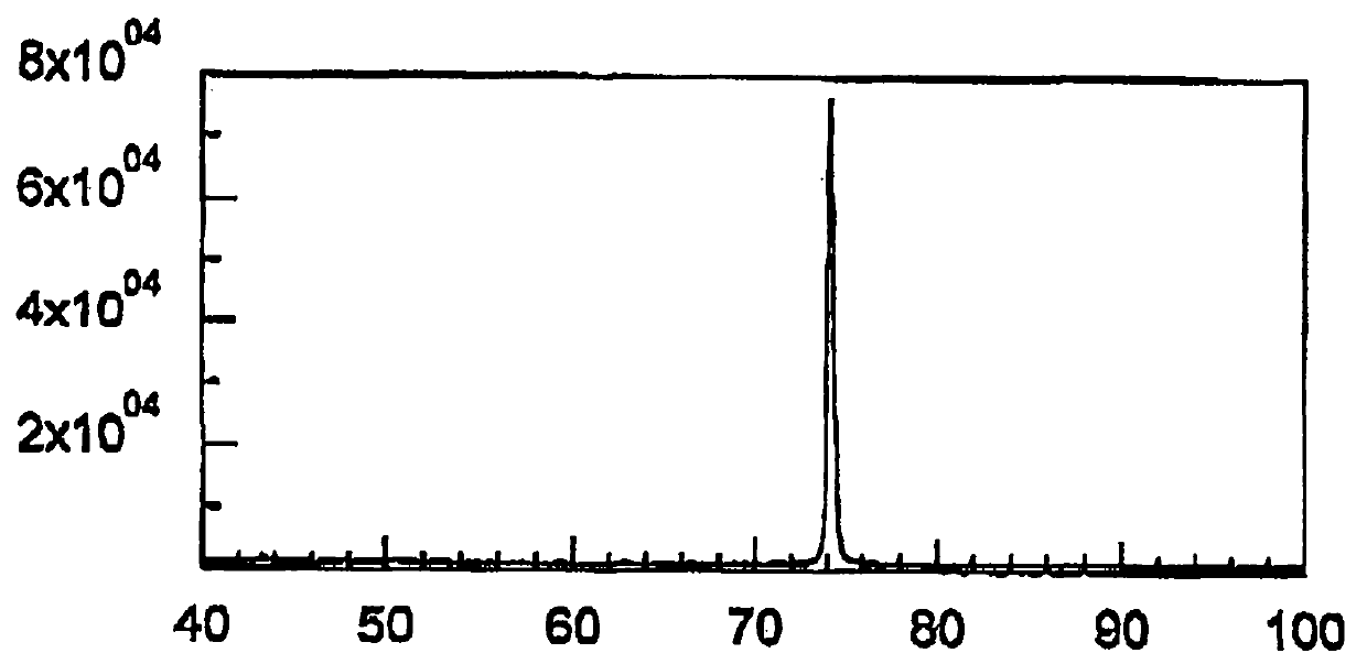
[0087] figure 1 An X-ray diffraction pattern showing the rough side of the untreated electrodeposited copper foil obtained in Example 1, figure 2 An X-ray diffraction pattern on the rough side of the untreated electrodeposited copper foil obtained in Comparative Example 1 is shown.

[0088] Depend on figure 1 It was observed that the intensity of the 220 diffraction line was strong, and thus it was found that a copper foil having a crystal structure with a strong {1...


PUM

PropertyMeasurementUnit
Thicknessaaaaaaaaaa

Abstract

The invention provides an electrolytic foil suitable for being used as an electrolytic foil material used by a TAB process. The electrolytic foil has a valley-shaped low rough surface which is not essentially formed at the side of a rough face, and has a high tensile strength and has no tinning peeling. The invention also provides a producing method of the electrolytic foil. A sulfuric acid-copper sulphate aqueous solution is used as an electrolyte, and direct current is circulated between two electrodes by means of an insoluble anode composed by titanium and a titanium-made cathode roller with respect to the anode. The insoluble anode is coated by a platinum group element or other oxides. Non-ionic and water-soluble macromolecules, sulfonates of active organic sulfur compounds, thioureas compounds and chloride ions are contained in the electrolyte. The obtained electrolytic foil is characterized in that the roughness of the rough face is below 2.0 Mum; a crystal structure whose orientation index obtained by the relative strength of 220 copper diffracted ray at the rough face side detected by an X-ray diffraction is over 5.0 is provided; the tensile strength of the electrolytic foil which is heated for an hour under the temperature of 180 DEG is over 500MPa.

Description

technical field [0001] The invention relates to an electrolytic copper foil, in particular to an electrolytic copper foil suitable for electronic circuit substrate materials and a manufacturing method thereof. Background technique [0002] As is well known, electrolytic copper foil is produced by the method described below using a plating technique. [0003] That is, an aqueous solution composed of sulfuric acid and copper sulfate is used as an electrolytic solution, and the electrolytic solution is filled between a cylindrical titanium drum as a cathode and an insoluble anode as an anode, and a direct current is passed between the two electrodes, thereby making copper precipitated on the surface of the cathode. At this time, the cathode drum rotates at a certain speed, and the deposited electrolytic copper is peeled off from the drum surface and continuously rolled up. In addition, for those skilled in the art, the surface of the peeled copper foil in contact with the dru...

Claims


Application Information

Patent Timeline
IPC IPC(8): C25D1/04C25D3/38
Inventor 佐野恭司真锅久德赤岭尚志冈本健
Owner FUKUKA METAL FOIL & POWDER CO LTD
Why Eureka
Try Eureka