Method and device for removing sulfur and carbon oxides from power plant flue gas in combination mode

A combined removal and oxidation technology, applied in the field of flue gas purification, can solve the problems of evaporation water consumption, complex flue gas coexisting components, waste of ash field resources, etc., and achieve the effects of reducing costs, good application prospects, and reducing energy consumption

Inactive Publication Date: 2011-09-07
NORTH CHINA ELECTRIC POWER UNIV (BAODING)
View PDF2 Cites 15 Cited by
  • Summary
  • Abstract
  • Description
  • Claims
  • Application Information

AI Technical Summary

Problems solved by technology

The reason is that the flue gas of the power plant has a high flow rate (about 1.2 million m3/h for the mainstream 300MW unit), high flow rate, high flue gas temperature (about 120 ℃ after ESP), relatively low CO2 volume fraction (12~15%), The characteristics of complex flue gas coexisting components (including PM, SO2, NOX and HCl), which make the use of conventional absorption processes have problems such as large system volume, high investment and operating costs
At present, the typical wet limestone gypsum method is widely used in the field of flue gas desulfurization. This technology is mature and reliable, but there are also problems that cannot be ignored. Among them, the utilization rate o

Method used


Image

  • Method and device for removing sulfur and carbon oxides from power plant flue gas in combination mode
  • Method and device for removing sulfur and carbon oxides from power plant flue gas in combination mode
  • Method and device for removing sulfur and carbon oxides from power plant flue gas in combination mode

Examples


Embodiment Construction

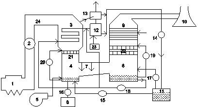
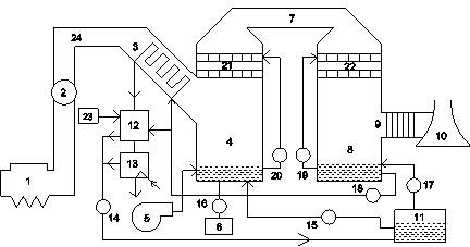
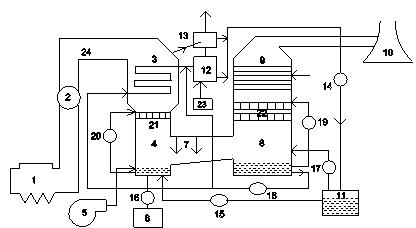
[0021] The method of the present invention uses ammonia water as an absorbent to integrally remove sulfur and carbon oxides in the flue gas of a power plant. After carbonization, the inlet temperature of the flue gas is 100-180°C, and the inlet temperature of the solution after decarburization is 20-30°C. After decarburization, the solution is preheated to 70-80°C and then enters the desorption tower for steam heating and analysis. After decarburization, the solution (the main component is ammonium bicarbonate) decomposes, ammonia and CO2 are separated, and a small part of the volatile and escaped ammonia gas and The analyzed CO2 enters the condenser together to remove escaped ammonia, and the separated CO2 is to be stored or converted for utilization. The ammonia water condensed by the condenser and the ammonia water resolved by the desorption tower are returned to the ammonia water storage tank in the removal process for recycling. The low-temperature flue gas cooled by hea...


PUM


Abstract

The invention relates to a method and a device for removing sulfur and carbon oxides from power plant flue gas in a combination mode, which are used for removing the sulfur and carbon oxides from the power plant flue gas at high efficiency and low consumption. The method comprises the following steps of: introducing high temperature flue gas subjected to electrostatic precipitation into a heat exchanger and heating decarburized solution in a removing process by using waste heat of the flue gas; feeding the heated decarburized solution into an absorption tower, decomposing ammonia water out and feeding the ammonia water back to an ammonia water storage tank; and allowing low temperature flue gas subjected to heat exchange to enter the removing process in combination with desulfuration and decarburization processes. The invention also provides the device for implementing the method. In the invention, the ammonia water is used as an absorbent, ammonia can be chemically circulated, and the cost of the absorbent is reduced; and the waste heat of the flue gas is effectively utilized to heat the decarburized solution, energy of a power plant can be utilized in a stepped way, and energy consumption during carbon capture is greatly reduced. The method and the device have the characteristics of high efficiency, high cleanness, low energy consumption, high integration of a desulfuration system and a decarburization system and have a wide application prospect on desulfuration and decarburization of a coal fired power plant.

Description

technical field [0001] The invention relates to a flue gas purification method, in particular to a method and a device for jointly removing sulfur and carbon oxides in power plant flue gas with high efficiency and low energy consumption, and belongs to the technical field of flue gas purification. Background technique [0002] There is no doubt that global warming is mainly caused by greenhouse gases such as CO2 emitted by humans burning coal and other fuels. The abnormal increase in global temperature caused by the excessive emission of greenhouse gases will bring many immeasurable adverse effects on natural ecosystems and human social life. According to data from the Organization for Economic Cooperation and Development and the International Energy Agency, the annual CO2 emissions of existing power plants are about 10.6 billion tons, accounting for 40.6% of the world's total emissions, of which coal-fired power plants are 7.6 billion tons, accounting for 72% of the emissio...

Claims


Application Information

Patent Timeline
IPC IPC(8): B01D53/78B01D53/50B01D53/62
CPCY02C10/04Y02A50/20Y02C20/40
Inventor 马双忱高莉崔基伟
Owner NORTH CHINA ELECTRIC POWER UNIV (BAODING)
Why Eureka
Try Eureka