Liquid forming method of composite material for closed die built-in resin flow distributor
A technology of flow distributor and composite material, applied in the field of resin matrix composite material liquid molding, can solve the problems of low fiber volume fraction, difficulty in obtaining product size and shape accuracy, and product complexity reduction, etc., to achieve cost reduction and greater freedom. , the effect of reducing the molding manufacturing process
- Summary
- Abstract
- Description
- Claims
- Application Information
AI Technical Summary
Problems solved by technology
Method used
Image
Examples
preparation example Construction
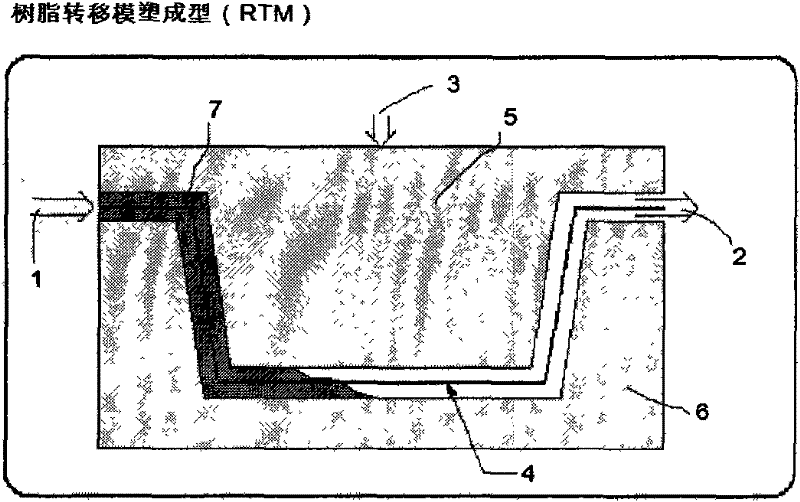
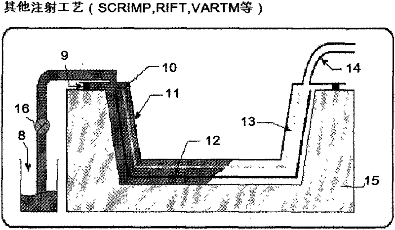
[0031] (1) First, the preparation of the resin flow distributor:
[0032] 1) Select the mold material according to the required molding pressure (0.05MPa~2.5MPa) and molding temperature (room temperature~300℃) of the composite material molding parts. Generally, the mold materials that can be selected are metal or non-metal (such as composite materials, ceramic cores, etc.) mold or wooden mandrel) to close the mold;
[0033]2) Then select a resin flow distributor that is close to the rigidity and hardness of the mold material. The resin flow distributor adopted in the technical solution of this patent is a metal fiber braided mesh (see Chinese patent, application number is 201020597767.4, and the name is "a kind of metal braided mesh resin flow distributor for composite material molding"). The preparation method is to select the material of the metal fiber according to the rigidity and strength of the resin flow distributor and the requirements of the molding temperature of th...
Embodiment 1
[0042] Example 1: Large RTM Formed Composite Laminate Structure Toughened "Out of Situ" Between Layers
[0043] (1) Design a stainless steel fiber braided mesh resin flow distributor with a double-layer structure. The surface layer of the resin flow distributor is a 100-mesh fine-mesh fabric, and the support layer is a coarse-mesh fabric with a thickness of 0.6mm. The two layers are assembled using conventional hot-press sintering techniques and then planarized using conventional hot-rolling techniques. See the utility model patent "A Metal Braided Mesh Resin Flow Distributor for Composite Material Forming" (application number 201020597767.4).
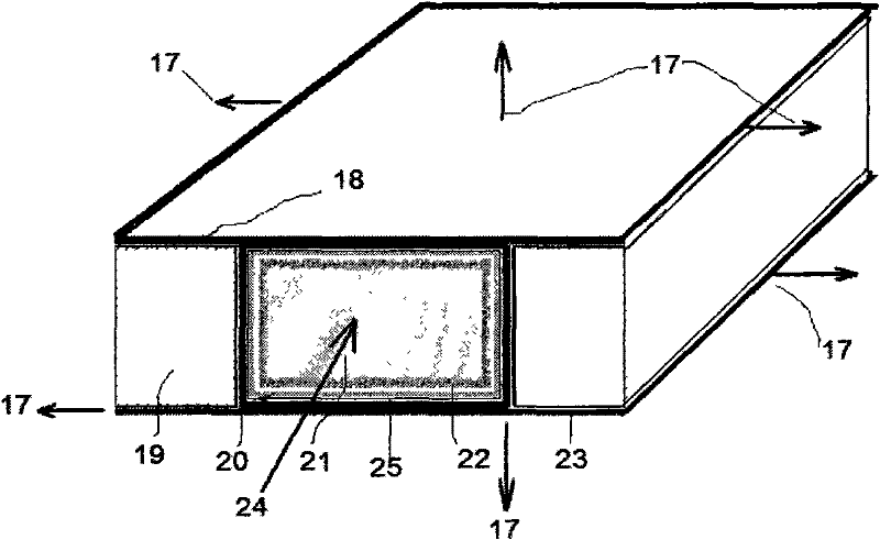
[0044] (2) The mold cavity size is 1500mm × 1500mm × 10mm, and the closed structure steel mold is split. The above-mentioned stainless steel fiber braided mesh resin flow distributor is laid on the whole area of the mold, and the resin flow distributor is installed on the side of the normal installation. For the center gate, set mul...
Embodiment 2
[0049] Example 2: High Viscosity Epoxy Large RTM Formed Composite Laminate Structure
[0050] (1) Thermoplastic resin PAEK toughened high-temperature epoxy resin (brand 5288, product of Beijing Aeronautical Materials Research Institute) resin has the characteristics of a multi-phase resin system, and its resin viscosity is relatively high, which is equivalent to the resin viscosity of prepreg grade, so The RTM injection process window is relatively narrow (short resin flow filling time, short resin process), so a high-rigidity 5-layer stainless steel fiber braided mesh resin flow distributor is designed, and its surface layer is 100 mesh fine mesh fabric. The support layer is 5 layers of coarse mesh fabric with a thickness of 0.5mm. As mentioned in the utility model patent "A Metal Braided Mesh Resin Flow Distributor for Composite Forming" (application number 201020597767.4), the entire resin flow distributor is assembled by hot pressing and sintering technology, and then flat...
PUM
| Property | Measurement | Unit |
|---|---|---|
| Fiber diameter | aaaaa | aaaaa |
| Mesh | aaaaa | aaaaa |
| Thickness | aaaaa | aaaaa |
Abstract
Description
Claims
Application Information
 - R&D
- Intellectual Property
- Life Sciences
- Materials
- Tech Scout
- Unparalleled Data Quality
- Higher Quality Content
- 60% Fewer Hallucinations
Browse by: Latest US Patents, China's latest patents, Technical Efficacy Thesaurus, Application Domain, Technology Topic, Popular Technical Reports.
© 2025 PatSnap. All rights reserved.Legal|Privacy policy|Modern Slavery Act Transparency Statement|Sitemap|About US| Contact US: help@patsnap.com


