High-frequency thyristor

A thyristor, high-frequency technology, applied in the direction of thyristor, electrical components, circuits, etc., can solve the problems of reducing application frequency and sacrificing efficiency, and achieve the effect of increasing the recombination center, large cathode area, and ensuring withstand voltage and dynamic characteristics

Inactive Publication Date: 2011-09-28
YICHANG SPAR POWER ELECTRONICS
View PDF5 Cites 5 Cited by
  • Summary
  • Abstract
  • Description
  • Claims
  • Application Information

AI Technical Summary

Problems solved by technology

The traditional high-power high-frequency melting furnace either sacrifices efficiency to reduce the application frequency, or relies on the application limitations broug

Method used


Image

  • High-frequency thyristor
  • High-frequency thyristor
  • High-frequency thyristor

Examples


Embodiment

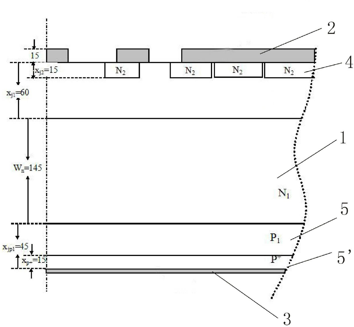
[0059] The high-frequency thyristor of the present invention is double-sided on the N-type (100) crystal orientation, low-resistance (40~50) Ω medium-irradiated single-crystal silicon wafer 1, and the P layer 5, 5' is double-sided and once vacuum closed tube diffused, that is, once P-type pure gallium diffusion, junction depth 55μm, single-side grinding 15μm after expansion P + Layer 5' is used as the anode side, oxidized and photolithographically etched on the other P-type side, and then phosphorous oxychloride N + Diffuse to form N 2 Zone 4, constituting an asymmetric thyristor P with a total thickness of 250 μm + P 1 N 1 P 2 N 2 basic structure, such as figure 1 shown;

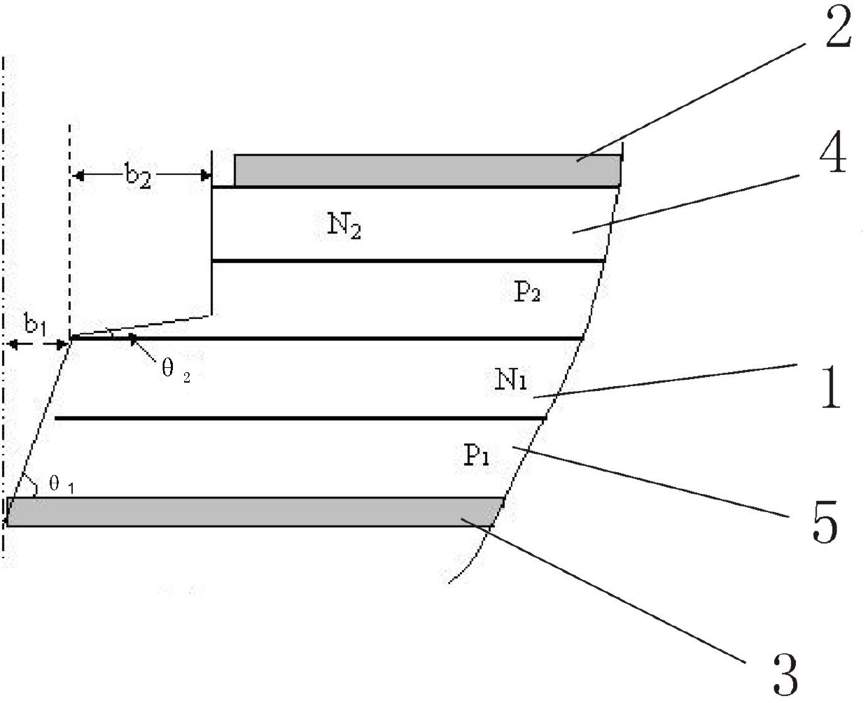
[0060] The shape of the table is changed from grinding angle shape to sandblasting shape, which is positive and negative angle structure. That is, the positive bevel is large-angle sandblasting, and the situation that the grinding angle can only be less than 35 degrees can be changed, and the positi...


PUM

PropertyMeasurementUnit
Thicknessaaaaaaaaaa
Thicknessaaaaaaaaaa
Thicknessaaaaaaaaaa

Abstract

The invention discloses a high-frequency thyristor. The high-frequency thyristor comprises a thyristor; a monocrystalline silicon wafer is formed by an asymmetric structure of P+P1N1P2N2, wherein the graph in an N2 region is an involute graph; in the monocrystalline silicon wafer, an N type (100) crystal orientation low resistance monocrystalline silicon wafer is used; a P<+> layer is formed by grinding and thinning a P layer; the thickness of the P<+> layer is 15 microns, and the thickness of the P layer is 60 microns. In the modelling surface of the monocrystalline silicon wafer, the grinding angle of a positive oblique angle theta1 is more than or equal to 60 degrees and less than or equal to 80 degrees; and the grinding angle of a negative oblique angle theta2 is more than or equal to 3.5 degrees and less than or equal to 4.5 degrees. A titanium nickel gold evaporation coating is arranged on the end face of the P<+> layer, and the thickness of Ti is 0.2 micron, the thickness of Ni is 0.5 micron and the thickness of Au is 0.1 micron. A method for manufacturing the high-frequency thyristor comprises the following steps of: arranging a diffusion P layer on double faces of the monocrystalline silicon wafer, wherein the P<+> layer is formed by grinding and thinning the P layer on one face, and an N2 region photolithography mask graph has an involute plug-in amplification gate pole structure; controlling the minority carrier lifetime tp for the monocrystalline silicon wafer and the N2 region photolithography mask graph by using a gold expansion method and an electron irradiation method respectively; evaporating by using an electron beam to form the titanium nickel gold evaporation coating; and blasting sand in a large angel for modeling. By the invention, the application frequency of the thyristor and the quality of products are improved, and the requirements of energy conservation and consumption reduction are met.

Description

technical field [0001] The invention relates to a power electronic device, in particular to a high-frequency thyristor. Background technique [0002] Traditional high-frequency thyristors have long turn-on and turn-off times, low operating frequency, very few operating currents can reach 1200A, and very few operating frequencies are around 8~10KHZ. For example, China Patent No.: 87208366 invention patent provides a high-frequency thyristor with an average on-state current of 200A and a working frequency of 10KHZ, which is suitable for intermediate frequency power supplies above 8KHZ; 10kHz, the average on-state current is 1200A. [0003] While the forward on-state average current IT(AV)=2500A, off-state repetitive peak voltage U DRM =1200V, reverse repetitive peak voltage U RRM =1200V, high-frequency thyristor with application frequency f =10KHz is a key device for high-frequency melting, high-frequency quenching and other equipment, and is a key device that is urgently n...

Claims


Application Information

Patent Timeline
IPC IPC(8): H01L29/04H01L29/06H01L29/74H01L21/332
Inventor 夏吉夫崔振森潘福泉
Owner YICHANG SPAR POWER ELECTRONICS
Why Eureka
Try Eureka