
Method for detection of trace impurities in polished subsurface damage layer of optical glass

A technology of sub-surface damage and optical glass, applied in the direction of color/spectral characteristic measurement, etc., can solve the problems of unrealistic detection, high detection cost, limited detection area, etc., to achieve flexible and controllable detection area, fast detection process and low detection cost low effect

Inactive Publication Date: 2011-12-21
NAT UNIV OF DEFENSE TECH
View PDF2 Cites 8 Cited by
  • Summary
  • Abstract
  • Description
  • Claims
  • Application Information

AI Technical Summary

Problems solved by technology

However, secondary ion mass spectrometry relies on high-precision testing instruments, which is costly and inefficient, and the detection area of ​​this method is limited (100 μm × 100 μm), which makes it impossible to detect the glass surface or a certain area on it

Method used


Image

  • Method for detection of trace impurities in polished subsurface damage layer of optical glass
  • Method for detection of trace impurities in polished subsurface damage layer of optical glass
  • Method for detection of trace impurities in polished subsurface damage layer of optical glass

Examples


Embodiment 1

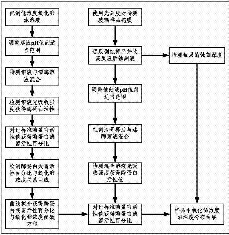
[0027] a kind of like figure 1 The detection method of trace impurity in the optical glass polishing subsurface damage layer of the present invention shown, comprises the following steps:

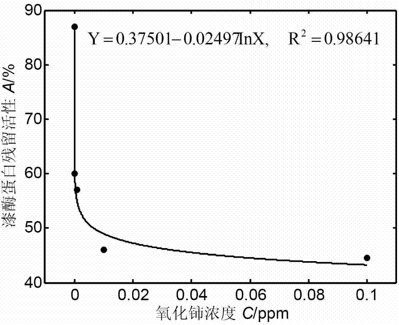
[0028] (1) Solution preparation: five different concentrations of cerium oxide (CeO 2 ) aqueous solution (concentration values ​​are 10 -7 ppm, 10 -4 ppm, 10 -3 ppm, 10 -2 ppm and 10 -1 ppm), and adjust the pH value of each cerium oxide aqueous solution to 4.5; take 3 mL of each of the five different concentrations of cerium oxide aqueous solutions, and then mix them with an equal volume of laccase solution, which contains 0.6 mL of crude enzyme (the fermented broth was centrifuged at 10000r / min for 10min and the supernatant was taken as the crude enzyme solution), 1mmol / L guaiacol substrate and 50mmol / L sodium succinate buffer solution to obtain five different solution samples;

[0029] (2) Determination of the residual activity percentage of the enzyme protein: put a series of solut...

Embodiment 2

[0035] a kind of like figure 1 The detection method of trace impurity in the optical glass polishing subsurface damage layer of the present invention shown, comprises the following steps:

[0036] (1)-(3): Steps (1)-(3) of this embodiment are the same as those of Embodiment 1;

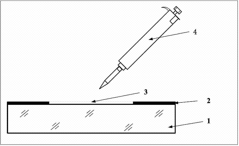
[0037] (4) Etching the glass to be tested: such as image 3 As shown, the K9 glass sample of Φ100mm×10mm polished by cerium oxide is selected as the glass sample 1 to be tested, and the photoresist 2 is used to mask the glass sample 1 to be tested, and the unmasked circular area with a central diameter of 50mm is used as the area to be tested 3. Then use the pipette 4 to introduce 10mL of etching solution into the unmasked area 3 of the glass sample to be tested 1, take it out for cleaning after an interval of 1min, and use a profiler to detect each etching of the glass sample to be tested depth, and collect the residual etching solution after each etching reaction;

[0038] (5) Detection of residua...


PUM


Abstract

The invention discloses a method for detecting a trace impurity in a damaged layer of a polished sub-surface of optical glass. The method comprises the following steps of: preparing a water solution which comprises rare-earth metal, and adjusting a pH value; mixing the water solution and a laccase solution, putting a mixed solution sample into a constant-temperature water bath, and thus obtainingthe percentage of enzyme protein residual activity of each sample by determining an enzyme protein activity value and a standard enzyme activity after reaction; according to the percentage and the concentration, corresponding to the percentage, of the rare-earth metal in each solution sample, fitting a relation curve; introducing etching liquid into a total surface of a glass sample to be detected or an unmasked local area to be detected by using a liquid-moving machine, detecting etching depth and collecting etching remained liquid after etching reaction; and adjusting the pH value of the etching remained liquid, mixing the etching remained liquid and the laccase solution, detecting the percentage of the enzyme protein residual activity in the etching remained liquid, and calculating theconcentration of the trace impurity according to the relation curve. The method has the advantages of accurate and reliable detection result and flexible and quick detection process.

Description

technical field [0001] The invention relates to a method for detecting trace impurities in optical glass, in particular to a method for detecting trace impurities in a polished damaged layer of optical glass. Background technique [0002] In strong light environments such as laser nuclear fusion and high-power lasers, the polishing impurities embedded in optical glass strongly absorb laser photon energy, causing laser damage to the substrate and film materials, which greatly reduces the service life of optical components. During the polishing process, the polishing impurities are introduced into the subsurface layer with decreasing concentration along the depth through redeposition. The maximum embedding depth is in the submicron to micron scale, and the impurity content is extremely low, and the peak concentration is in the order of ppm. Energy spectroscopy and inductively coupled plasma Detection methods such as atomic emission spectrometry are powerless to this. At prese...

Claims


Application Information

Patent Timeline
IPC IPC(8): G01N21/31
Inventor 王卓王林梁科山杨军宏沈侃徐小军尚建忠戴一帆李圣怡
Owner NAT UNIV OF DEFENSE TECH
Learn More