Fluid bed electrode direct carbon fuel cell device

A fuel cell and fluidized bed technology, used in solid electrolyte fuel cells, fuel cell additives, battery electrodes, etc., can solve the problems of low heat transfer efficiency of fixed bed reactors, difficult to meet requirements, and continuous supply of carbon fuel. It is convenient to collect current, increase heat transfer effect, and improve performance effect

Inactive Publication Date: 2012-01-18
TSINGHUA UNIV
View PDF4 Cites 40 Cited by
  • Summary
  • Abstract
  • Description
  • Claims
  • Application Information

AI Technical Summary

Problems solved by technology

[0004] The structure of the traditional fixed bed reactor is simple, and there are few factors affecting the flow, which is conducive to the study of the reaction mechanism of SO-DCFC. However, the total reaction rate of the fixed bed reactor is mainly controlled by the material diffusion process, which is the rate controlling step of the carbon gasification reaction process. , while facing the problem of continuous supply of carbon fuel after a period of reaction
For the carbon gasification reaction process, the gasification reaction of carbon (1) is a strong endothermic reaction, while the electrochemical oxidation reaction of CO (2) is a strong exothermic reaction, the heat transfer and matching of the reactor heat transfer The rate puts forward higher requirements, and the heat transfer efficiency of the fixed bed reactor is low, so it is difficult to meet the requirements

Method used


Image

  • Fluid bed electrode direct carbon fuel cell device
  • Fluid bed electrode direct carbon fuel cell device
  • Fluid bed electrode direct carbon fuel cell device

Examples


Embodiment 1

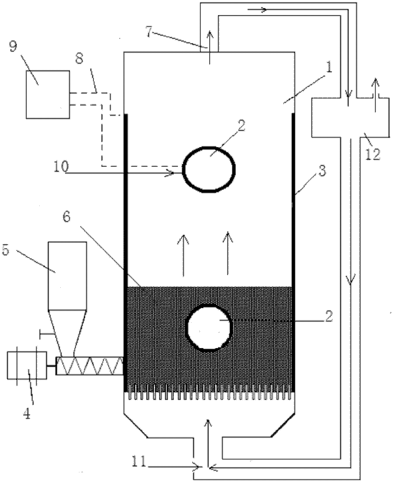
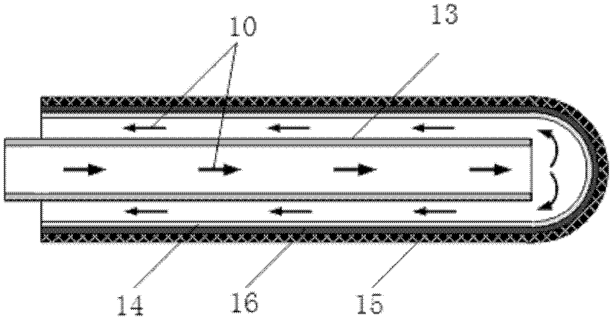
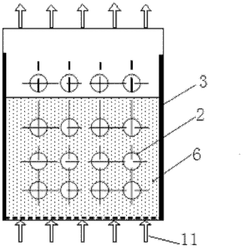
[0022] Fluidized bed electrode direct carbon fuel cell device, which includes a fluidized bed 1, two or more tubular single cells 2, a collector plate 3, a composite carbon fuel 6, a gas circulation device 12, and a screw feeder 4, fuel tank 5 (such as figure 1 shown); the tubular single battery is a blind tube type (such as figure 2 As shown), the open end protrudes from the fluidized bed 1, and the closed end is placed inside the fluidized bed 1. The inner side of the tubular cell is the cathode 14, the outer side is the anode 15, and the middle is the solid oxide electrolyte 16. The tubes 13 are inserted into the battery in parallel, and the layout of the tubular cells is arranged in a row (such as image 3 Shown); collecting plate 3 is placed on the inner wall of fluidized bed 1; composite carbon fuel 6 is filled in the bottom of fluidized bed 1, communicates with screw feeder 4 and fuel tank 5 outside fluidized bed 1; composite carbon fuel 6 is the carbon fuel added to...

Embodiment 2

[0025] Fluidized bed electrode direct carbon fuel cell device, which includes a fluidized bed 1, two or more tubular single cells 2, a collector plate 3, a composite carbon fuel 6, a gas circulation device 12, and a screw feeder 4, fuel tank 5 (such as figure 1 shown); the tubular single battery is a through-tube type (such as Figure 4 As shown), both ends extend out of the fluidized bed 1, the inner side of the tubular single battery is the cathode 14, the outer side is the anode 15, and the middle is the solid oxide electrolyte 16, and the layout of the tubular single battery is in a parallel arrangement (such as image 3 Shown); collecting plate 3 is placed on the inner wall of fluidized bed 1; composite carbon fuel 6 is filled in the bottom of fluidized bed 1, communicates with screw feeder 4 and fuel tank 5 outside fluidized bed 1; composite carbon fuel 6 is the carbon fuel added to the ion conductor, the carbon fuel includes graphite, carbon black, coke, coal and the m...


PUM


Abstract

The invention discloses a fluid bed electrode direct carbon fuel cell device, which belongs to the technical field of clean energy. The device comprises a fluid bed, two or more tubular single cells, collector plates, a composite carbon fuel, a gas circulating device, a screw feeder and a fuel tank. In the device, a conductor catalyst is added into a solid carbon fuel on the basis of a solid oxide direct carbon fuel cell to expand a direct electrochemical reaction interface of carbon from a two dimension to a three dimension and promote the gasification reaction of the carbon, thereby improving the performance of the cell; the collector plates are distributed on the wall surface of a reactor, so current is convenient to collect; and simultaneously, a fluid bed reactor forms a fluid bed electrode to further enhance heat transfer and mass transfer in the electrode, so not only problems about feeding are solved, but also the performance of the solid oxide direct carbon fuel cell is further improved.

Description

technical field [0001] The invention belongs to the technical field of clean energy, and in particular relates to a fluidized bed electrode direct carbon fuel cell device. Background technique [0002] my country is the largest coal producer and consumer in the world, and its coal consumption accounts for more than 70% of the total primary energy, of which more than 50% of the coal is used for thermal power generation. At the same time, coal also occupies a major position in my country's power structure. In 2009, more than 74.6% of my country's total installed capacity was thermal power generation, of which coal-fired power generation accounted for 95%. The coal-based energy structure will not change much in a short period of time. However, at present, my country's coal-fired power generation efficiency is low, energy waste and environmental pollution are serious; at the same time, as the world's CO 2 As the largest emitter country, we are facing a huge CO 2 In addition, ...

Claims


Application Information

Patent Timeline
Patent Type & Authority Applications(China)
IPC IPC(8): H01M8/10H01M8/04H01M4/86
CPCY02E60/521Y02E60/50
Inventor 史翊翔蔡宁生王洪建
Owner TSINGHUA UNIV
Why Eureka
Try Eureka