
Panoramic sight system for turning shoot gun

A technology for sighting systems and guns, applied in aiming devices, weapon accessories, offensive equipment, etc., can solve the problems of unavoidable influence of system working performance, and achieve improved performance and aiming accuracy, reasonable man-machine relationship, and obvious economy. effect of benefit

Inactive Publication Date: 2012-03-28
白世忠
View PDF6 Cites 6 Cited by
  • Summary
  • Abstract
  • Description
  • Claims
  • Application Information

AI Technical Summary

Problems solved by technology

[0004] The core technology of the aiming system - video technology (camera + liquid crystal display), cannot avoid the impact of the natural environment (high, low temperature, rain, snow, sand and dust) on the system A series of technical support issues such as the impact of work performance, mean time between failures (MTBF) and service guarantee, etc., will bring a lot of trouble to users

Method used


Image

  • Panoramic sight system for turning shoot gun
  • Panoramic sight system for turning shoot gun
  • Panoramic sight system for turning shoot gun

Examples


Embodiment 1

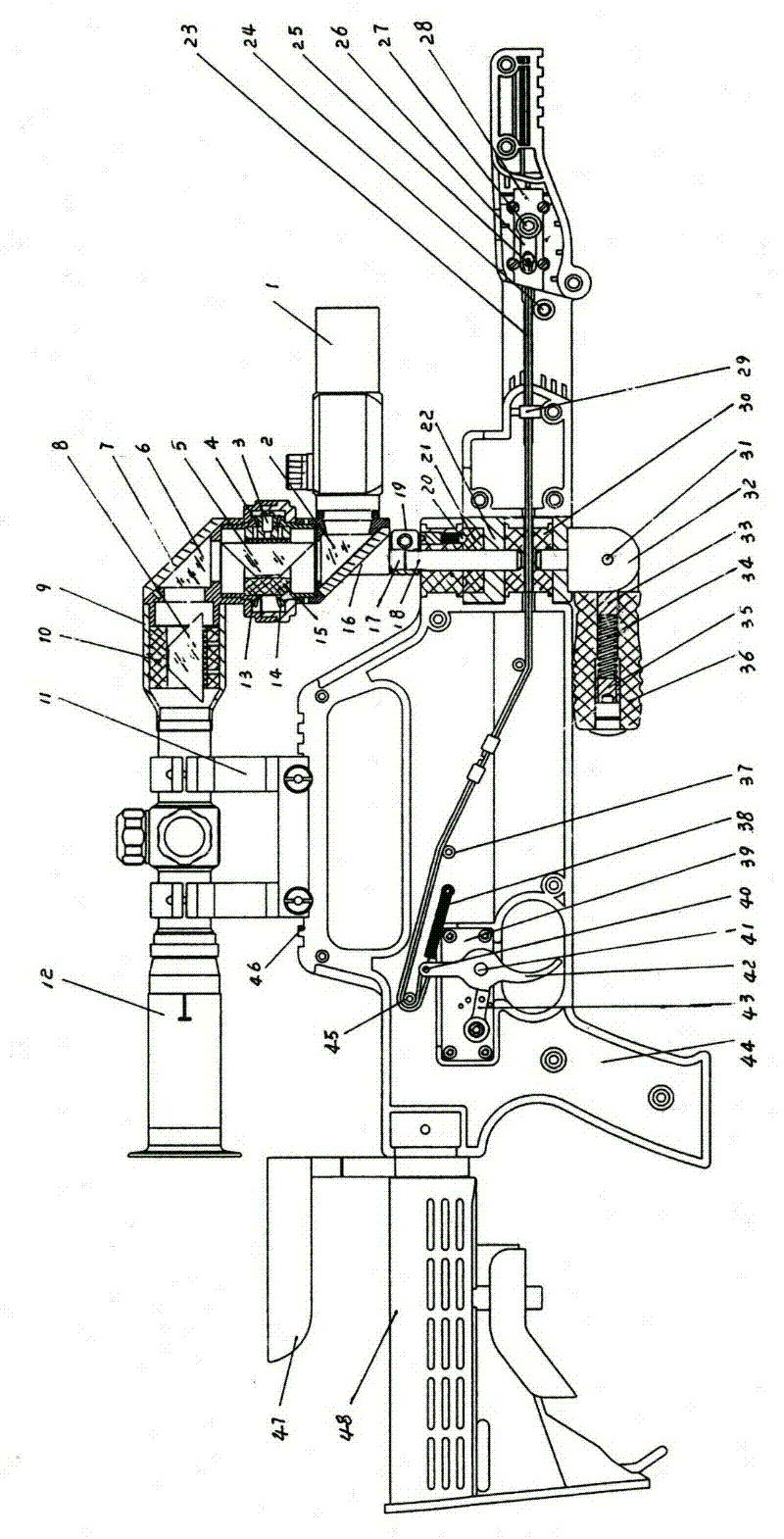
[0016] Reference figure 1 , This is a schematic diagram of the structure of the hand-held light weapon free-line shooting and sighting system of the present invention.

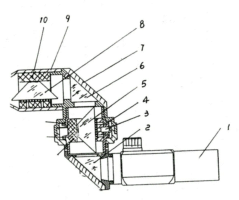
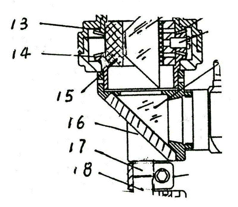
[0017] As shown in the figure, the structure of the sighting system consists of the following components: 1 is the red dot gunsight, 2 is the first right-angle prism, 3 is the satellite gear shaft, 4 is the satellite gear, 5 is the first dome prism, 6 is the The second right-angle prism, 7) is the upper prism holder, 8 is the second dome prism, 9) is the lens tube, 10 is the lens holder, 11 is the bracket, 12 is the gun sight, 13 is the sun wheel, 14 is Under the sun gear, 15 is the rotating sleeve, 16 is the lower prism seat, 17 is the lens shaft, 18 is the hinge shaft, 19 is the chain shaft tightening sleeve, 20 is the positioning pin, 21 is the positioning seat, 22 is the gun clamp, 23 is the The firing rope, 24 is the button, 25 is the slider pin, 26 is the firing slider, 27 is the firing shaft, 28 is the fir...

Embodiment 2

[0025] Change the first right-angle prism 2 and the right-angle prism into a "Dove prism" 5 (antimony-shaped prism) to overcome the pupil of the field of view.

[0026] Add a red dot gunsight 1 in front of the right-angle prism, so that the aiming base point is not affected by the optical axis of the imaging optical system, so that the aiming accuracy is improved;

[0027] The variable angle handle 36 is added, and the man-machine efficiency is significantly improved. The linkage trigger adjustment spring 38 is added to make the linkage trigger and the pistol trigger consistent in action, which is different from the existing technology;

[0028] The linkage trigger 42 is obviously different from the prior art.

[0029] The corner positioning mechanisms 20 and 21 are built-in three-point marble positioning, which is different from the prior art.


PUM


Abstract

The invention relates to a panoramic sight system for a turning shoot gun. The sight system comprises a viewing optical system with a red spot sighting telescope, a differential mechanism and a white light imaging system; a platform operating mechanism of the sight system is fixedly connected with a weapon fighting mechanism of the sight system through upper and lower rotating shafts, and the rotating shafts are driven by an electric corner actuating mechanism; weapons such as guns and the like are fixed on a fixing bracket of the weapon fighting mechanism, and a gun firing mechanism steel cable in the bracket is controlled by the platform operating mechanism combined with a trigger and is provided with firing insurance; and an image / video and audio wireless transmitter, a tactical laser and a tactical light can be installed on a tactical guide rail on the weapon fighting mechanism. The system provided by the invention is improved on the basis of the traditional gun turning aimed fire tactical operating platform; because a Dove prism and a red spot sighting telescope are additionally provided, the pointing accuracy of the optical system is increased; and because a free rotating target is additionally provided, the man-machine relationship is more reasonable, and the platform is more applicable. Thus, the system provided by the invention has obvious economic benefits.

Description

technical field [0001] The invention relates to a peripheral viewing and aiming system for a turning shooting gun, which is used for line-changing aiming of pistols and miniature submachine guns, and belongs to the field of optics and mechanics. Background technique [0002] At present, all hand-held light weapons are aimed and shot in a straight line through mechanical or optical sights. When in a tactical environment with a blind spot for visual observation, the shooter can only aim at the baseline without the gun itself and shoot blindly. In order to solve the problem of concealed aiming and turning shooting under special tactical conditions, products such as turning guns and changing line shooting weapon platforms that control pistol turning and shooting have appeared at home and abroad. The main principle is to fix the pistol on an operating platform. , control the angle of the pistol and camera and the trigger of the pistol by manual and electric means, and observe and...

Claims


Application Information

Patent Timeline
IPC IPC(8): F41G1/46
Inventor 白世忠
Owner 白世忠
Learn More