
Heavy oil hydrogenation conversion method

A technology for heavy oil hydrogenation and heavy oil, which is applied in hydrocarbon oil cracking, petroleum industry and other directions, can solve the problems of increasing heavy oil processing cost, large reactor wall thickness, and difficult manufacturing, so as to reduce the cost of heavy oil hydrogenation conversion and shorten the reaction time. time, the effect of improving utilization

Active Publication Date: 2014-03-26
CHINA PETROLEUM & CHEM CORP +1
View PDF4 Cites 0 Cited by
  • Summary
  • Abstract
  • Description
  • Claims
  • Application Information

AI Technical Summary

Problems solved by technology

[0006] The existing heavy oil direct hydrogenation conversion technology uses large-scale high-temperature and high-pressure reactors, which have large wall thickness, heavy tonnage, and difficult manufacturing. In addition, in order to improve the three-phase mass transfer process of reaction materials, high-temperature, high-pressure multi-phase circulation is used. Pumps to circulate the reaction materials, increasing the cost of heavy oil processing

Method used


Image

  • Heavy oil hydrogenation conversion method
  • Heavy oil hydrogenation conversion method

Examples


Embodiment 1

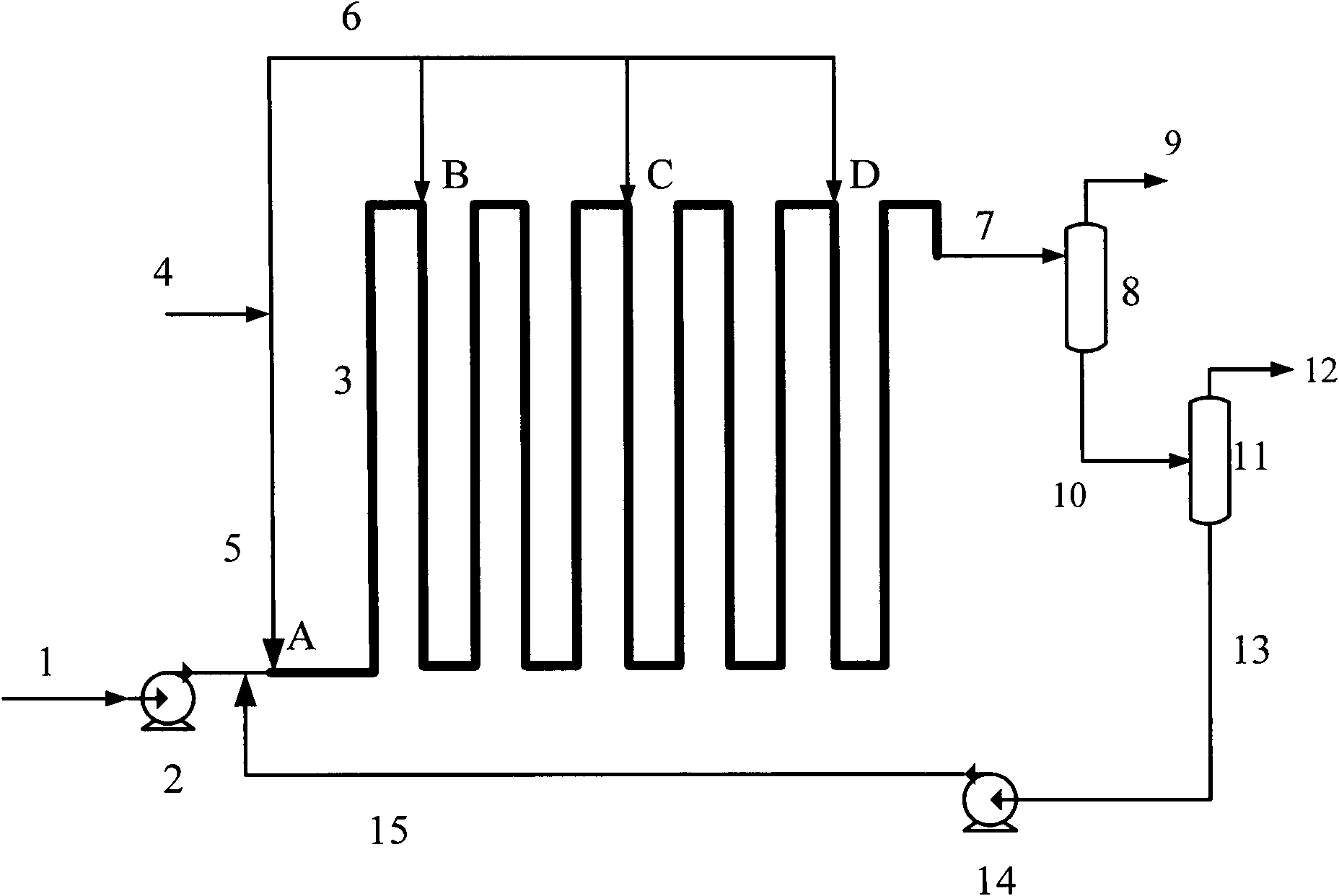
[0035] Using the process flow shown in the accompanying drawing, will contain 1000ppm active metal FeSO 4 The heavy oil raw material of the slurry catalyst is sent into the tubular reactor with a flow rate of 10,000kg / h using a high-pressure pump. The flow state in the tubular reactor is turbulent, with a diameter of Φ55mm, a length of 500m, and a reaction temperature of 380- 460°C, pressure 16MPa. Hydrogen is respectively from the entrance of the tubular reactor, 60m (accounting for 12% of the total length), 150m (accounting for 30% of the total length), 250m (accounting for 50% of the total length) and 350m (accounting for 70% of the total length) from the entrance of the tubular reactor Injection at five points at , the molar ratios of injected hydrogen to heavy oil are 5, 4.5, 4, 3.5 and 3, respectively. The reaction product is analyzed, and the heavy oil conversion rate is calculated according to the following formula,

[0036]

[0037] The obtained heavy oil convers...

Embodiment 2

[0039] Using the process flow shown in the accompanying drawing, the heavy oil raw material is mixed with 100ppm MoS 2 Mix with 500ppm FeS to form heavy oil slurry. The heavy oil slurry is sent into a tubular reactor with a flow rate of 20,000kg / h using a high-pressure pump. The flow state in the tubular reactor is turbulent, with a diameter of Φ219mm, a length of 250m, and a reaction temperature of 400-480°C. The pressure is 30MPa. Hydrogen respectively from the entrance of the tubular reactor, 40m (accounting for 16% of the total length), 90m (accounting for 36% of the total length), 150m (accounting for 60% of the total length) and 200m (accounting for 80% of the total length) from the entrance of the tubular reactor Inject at 5 points, and the molar ratios of the amount of hydrogen injected to the heavy oil slurry are 10, 2.5, 2.5, 2.5 and 2.5 respectively. The conversion rate of the obtained heavy oil was 92%.


PUM

PropertyMeasurementUnit
diameteraaaaaaaaaa
diameteraaaaaaaaaa
densityaaaaaaaaaa

Abstract

A heavy oil hydrogenation conversion method. Under a condition of a heavy oil hydrogenation conversion reaction, a heavy oil raw material mixture containing heavy oil raw materials and a catalyst is allowed to contact hydrogen in a tubular reactor, and heavy oil macromolecules are converted into gas and liquid hydrocarbon reaction products, wherein the contact between hydrogen and the heavy oil raw material mixture is performed at least twice. The invention adopts a tubular reaction which has a small diameter and is simple in manufacturing and installation; by means of multi-time hydrogen injection, the invention reduces the hydrogen excessive amount during the reaction, and improves the utilization rates of hydrogen and the reactor. The heavy oil direct hydrogenation conversion method provided by the invention can improve the efficiency of heavy oil direct hydrogenation conversion, thus reduces cost for heavy oil hydrogenation conversion, and improves the technical economy of heavy oil hydrogenation conversion.

Description

technical field [0001] The present invention relates to a process for treating hydrocarbon oils in the presence of hydrogen, more particularly to a process for the hydroconversion of heavy oils in tubular reactors. Background technique [0002] With the increasing shortage of oil resources in the world and the high price of crude oil, how to convert the abundant heavy oil resources into clean transportation fuels has become an important research direction of heavy oil processing. Currently, there are two main ways to process heavy oil: decarburization or hydrogenation. Delayed coking is a typical decarbonization process, which can process various low-quality residues, but its liquid products have low yield and poor quality, and the application of petroleum coke is also limited. Therefore, in order to improve the yield of light fuel oil in refineries, hydrogenation technology is widely used to treat residual oil or heavy oil, mainly including fixed bed, moving bed, ebullatin...

Claims


Application Information

Patent Timeline
Patent Type & Authority Patents(China)
IPC IPC(8): C10G47/00
Inventor 申海平杨元一龙军吴治国王卫平
Owner CHINA PETROLEUM & CHEM CORP
Learn More