Switched capacitor clock generator

A technology of clock generators and switched capacitors, applied in sinusoidal oscillation train generators, pulse generation, electrical components, etc., can solve problems such as poor precision, complex circuits, temperature characteristics, process stability, and poor power supply suppression capabilities, and achieve structural simple effect

Inactive Publication Date: 2012-04-25
SUZHOU R&D CENT OF NO 214 RES INST OF CHINA NORTH IND GRP
View PDF2 Cites 6 Cited by
  • Summary
  • Abstract
  • Description
  • Claims
  • Application Information

AI Technical Summary

Problems solved by technology

The RC oscillator has a simple structure and is easy to implement, but its accuracy is poor, and it varies greatly with temperature and power supply voltage. It is generally used in occasions that do not require high clock accuracy.
In order to obtain better precision, the oscillator adopts a r

Method used


Image

  • Switched capacitor clock generator
  • Switched capacitor clock generator
  • Switched capacitor clock generator

Examples


Embodiment 1

[0028] Embodiment one: see attached figure 1 shown.

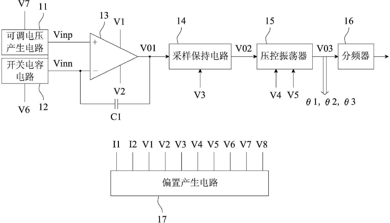
[0029] A switched capacitor clock generator, which includes an adjustable voltage generating circuit 11, a switched capacitor circuit 12, an integrator 13, a sample and hold circuit 14, a voltage-controlled oscillator 15, a frequency divider 16, and a bias generating circuit 17.

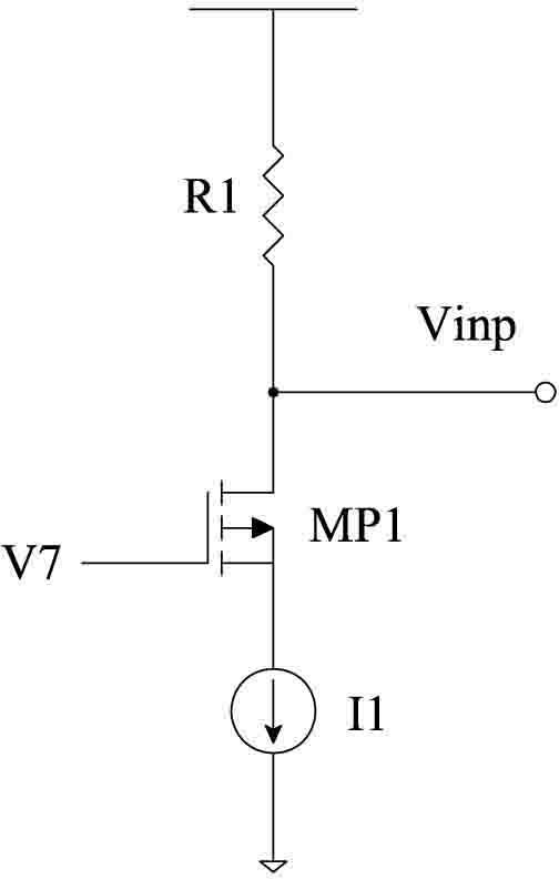
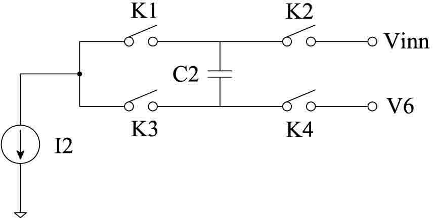
[0030] The adjustable voltage generating circuit 11 and the switched capacitor circuit 12 are respectively connected to the two input terminals of the integrator 13 . The adjustable voltage generating circuit 11 is used to generate a voltage for controlling the center frequency of the voltage-controlled oscillator 15 , and at the same time provide a suitable non-inverting terminal voltage for the switched capacitor circuit 12 . The switched capacitor circuit 12 is used to generate a discontinuous current.

[0031] The integrator 13 generates a sawtooth output voltage, and its output terminal is connected to the sample-and-hold circuit 14 . The ...


PUM


Abstract

The invention relates to a switched capacitor clock generator that comprises an adjustable voltage generation circuit, a switched capacitor circuit, an integrator, a sampling hold circuit, a voltage controlled oscillator, a frequency divider and a bias generation circuit. The adjustable voltage generation circuit and the switched capacitor circuit are respectively connected with input terminals of the integrator, and the adjustable voltage generation circuit generates a voltage that is used for controlling a center frequency of the voltage controlled oscillator; the switched capacitor circuit generates discontinuous currents; the integrator generates a sawtooth wave output voltage and the output terminal of the integrator is connected with the sampling hold circuit; an output terminal of the sampling hold circuit is connected with the voltage controlled oscillator and the sampling hold circuit is used for providing a control signal for the voltage controlled oscillator; and the voltage controlled oscillator generates a frequency signal and the output terminal of the voltage controlled oscillator is connected with the frequency divider. According to the invention, the structure of the generator is simple; a clock signal with high precision can be generated; and the temperature characteristic, the technology stability and the power supply inhibition capability of the provided generator are better than those of an existing clock generator.

Description

technical field [0001] The invention relates to a clock generator, in particular to a switched capacitor clock generator based on CMOS technology. Background technique [0002] In various electronic systems, the clock signal is an indispensable reference signal. It has a wide range of applications from clock generation in microprocessors to carrier synthesis in cellular phones, as well as measurement, remote control and automatic control. Usually, the clock signal in the electronic system generates a reference clock signal through a quartz crystal oscillator set outside the electronic system, and then the phase-locked loop in the system outputs a higher frequency clock signal for the internal circuit based on the reference clock signal. use. However, although a more accurate clock signal can be generated by using a quartz crystal oscillator to generate a clock signal, this method requires pins to receive the reference clock signal, which will cost a higher pin cost. [000...

Claims


Application Information

Patent Timeline
IPC IPC(8): H03K3/011H03K3/80
Inventor 龙善丽贺克军唐兴刚陈超王丽
Owner SUZHOU R&D CENT OF NO 214 RES INST OF CHINA NORTH IND GRP
Why Eureka
Try Eureka