
Blade-breakage-resisting surface coating cutting tool with excellent performance of hard coating layer

A cutting tool, surface coating technology

Active Publication Date: 2012-05-09
MITSUBISHI MATERIALS CORP
View PDF7 Cites 18 Cited by
  • Summary
  • Abstract
  • Description
  • Claims
  • Application Information

AI Technical Summary

Problems solved by technology

[0018] The current situation is as follows: in recent years, the performance of cutting equipment has been significantly improved, and on the other hand, the demand for labor saving and energy saving in cutting processing, and further cost reduction has been strengthened. With this, cutting processing has gradually tended to increase in speed, but In the above-mentioned conventional coated tools 1 and 2, there is no problem when they are used for continuous cutting or interrupted cutting under normal conditions such as steel or cast iron, but they are especially used for high heat generation and impact and When an intermittent load acts on the blade under high-speed intermittent cutting conditions, the high-temperature strength and impact resistance of the hard coating layer are not sufficient. In addition, once the hard coating layer cracks due to impact, etc., the layer The internal stress in the steel promotes the development of cracks, and it is prone to chipping and defects. As a result, the service life is reached in a short period of time.

Method used


Image

  • Blade-breakage-resisting surface coating cutting tool with excellent performance of hard coating layer
  • Blade-breakage-resisting surface coating cutting tool with excellent performance of hard coating layer
  • Blade-breakage-resisting surface coating cutting tool with excellent performance of hard coating layer

Examples


Embodiment Construction

[0107] Next, the covering tool of the present invention will be specifically described by way of examples.

[0108] As raw material powders, prepare the powders shown in Table 1 each having an average particle diameter of 1 to 3 μm, mix these raw material powders into the compounding composition shown in Table 1, add paraffin, ball mill and mix in acetone for 24 hours, and dry under reduced pressure. Afterwards, the green compact is extruded into a predetermined shape with a pressure of 98 MPa, and vacuum sintered under the condition of maintaining a predetermined temperature in the range of 1370-1470 ° C for 1 hour in a vacuum of 5 Pa. After sintering, the green compact is passed A honing process of R: 0.07 mm was applied to the blade portion to produce WC-based cemented carbide tool bases 1 to 10 each having a multi-blade shape specified in ISO·CNMG160412.

[0109] In addition, as raw material powders, powders shown in Table 2 each having an average particle diameter of 0.5 ...


PUM

PropertyMeasurementUnit
thicknessaaaaaaaaaa
thicknessaaaaaaaaaa

Abstract

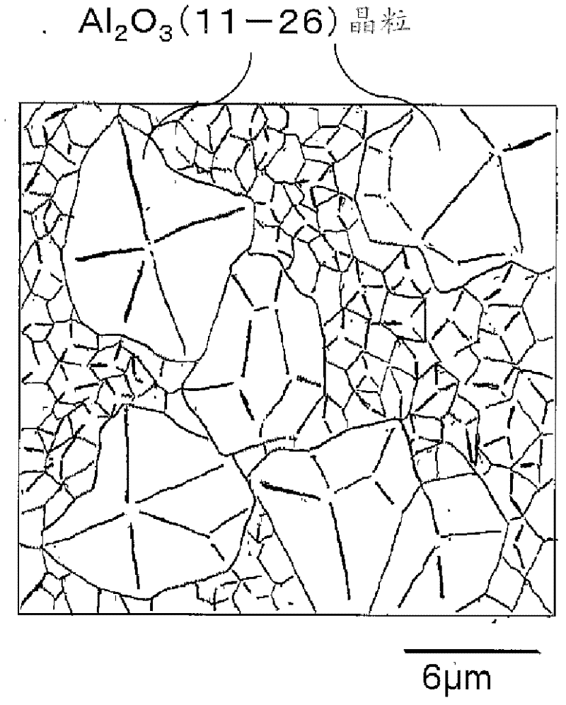
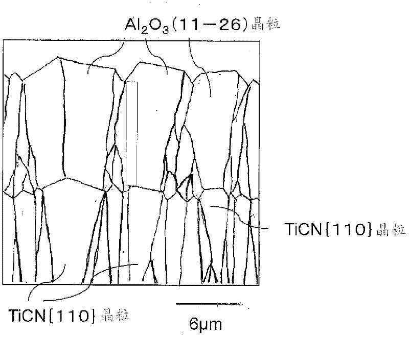
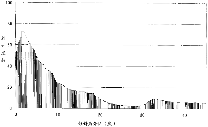
The present invention provides a blade-breakage-resisting surface coating cutting tool with excellent performance of a hard coating layer. A Ti compound layer which at least comprises a TiCN layer is coated on the surface of a tool substrate as a lower layer (a). In the surface coating cutting tool in which an alpha Al2O3 layer is used as an upper layer (b), for the TiCN layer of the lower layer, when an included angle of a normal line of a surface [110] is formed by a field emission scanning electron microscope and is prepared to an inclination angle number distribution graph, the TiCN particles [110] of the inclination angle in the range of 0-10 DEG accounts for more than 50% of the whole particles. Additionally, for the alpha type Al2O3 layer of the upper layer, when the inclination angle which is formed by the normal line of a surface (0001) is measured and prepared to an inclination angle number distribution graph, the Al2O3 crystal particles with the inclination angle in 35-45 DEG accounts for more than 60% of the whole particles. Furthermore when observed in a surface which is vertical to the layer thickness direction, crystal particles of the Al2O3 (11-26) are coarse and large, and average crystal particle diameter of the crystal particles of the Al2O3 (11-26) is 2-5 times of the crystal particles except for the Al2O3 (11-26).

Description

technical field [0001] The present invention relates to a surface-coated cutting tool (hereinafter referred to as a coated tool), especially for various steel or cast iron, etc. The hard coating layer also exhibits excellent chipping resistance in long-term use when cutting the cutting material. Background technique [0002] In the past, it is generally known that the surface of a substrate composed of tungsten carbide (hereinafter referred to as WC)-based cemented carbide or titanium carbonitride (hereinafter referred to as TiCN)-based cermet (hereinafter these are collectively referred to as a tool substrate) is generally known. A coated tool that is plated to form a hard coating layer consisting of the following (a) and (b), [0003] (a) The lower layer is composed of Ti carbide (hereinafter represented by TiC) layer, nitride (hereinafter also represented by TiN) layer, carbonitride (hereinafter represented by TiCN) layer, carbon oxide (hereinafter represented by TiCO) ...

Claims


Application Information

Patent Timeline
Patent Type & Authority Applications(China)
IPC IPC(8): B23B27/14B23C5/16B23P15/28C23C16/30
Inventor 富田兴平龙冈翔长田晃中村惠滋
Owner MITSUBISHI MATERIALS CORP
Learn More