

Composite abrasive grain as well as preparation method and application thereof
A technology of composite abrasive grains and polymethacrylate, which is applied in the direction of polishing compositions containing abrasives, etc., and can solve problems such as the core-shell structure of composite abrasive grains is not ideal
- Summary
- Abstract
- Description
- Claims
- Application Information
AI Technical Summary
Problems solved by technology
Method used
Image

Examples
Embodiment 1
[0030] Embodiment 1: the preparation of PS latex
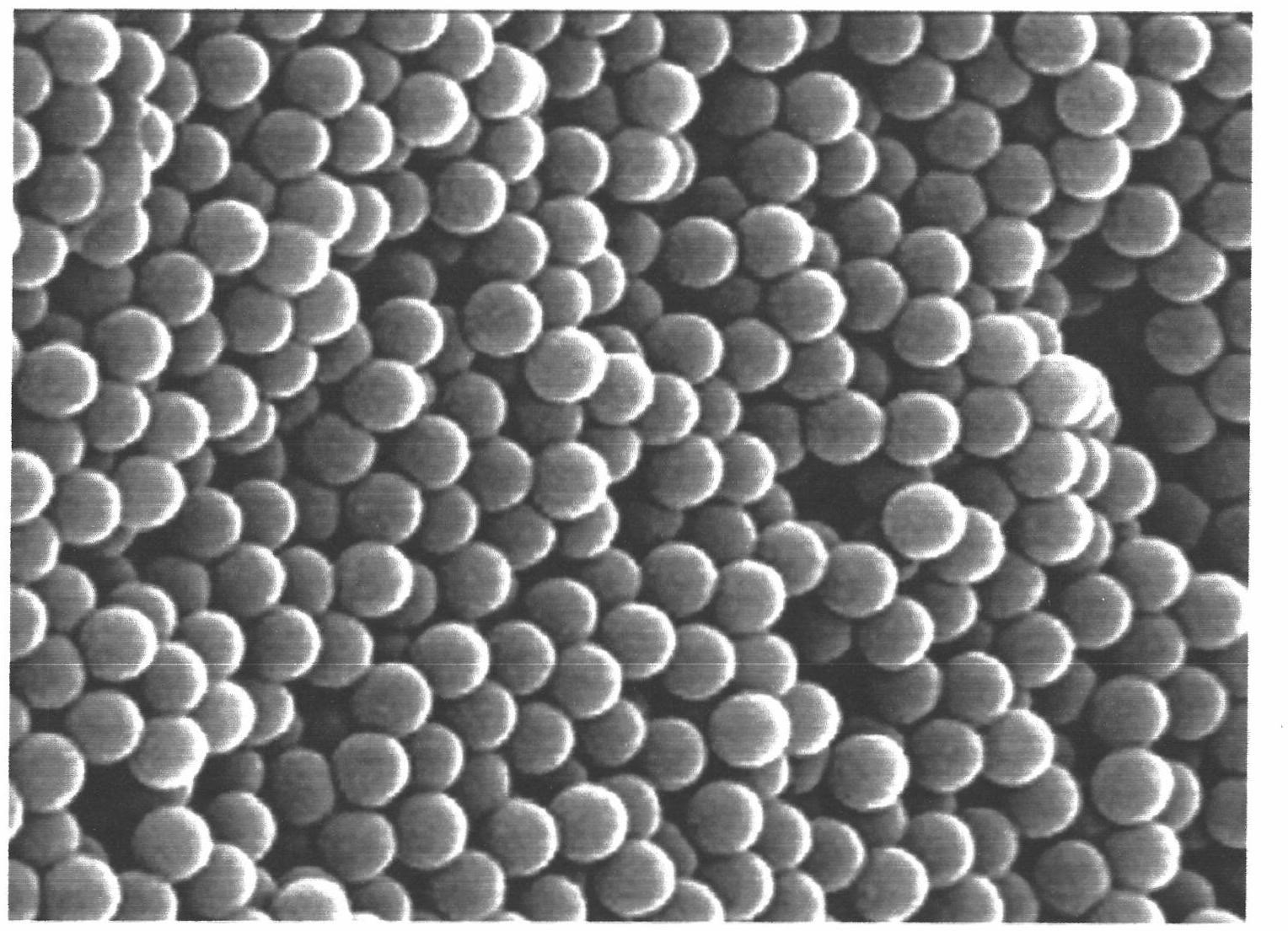
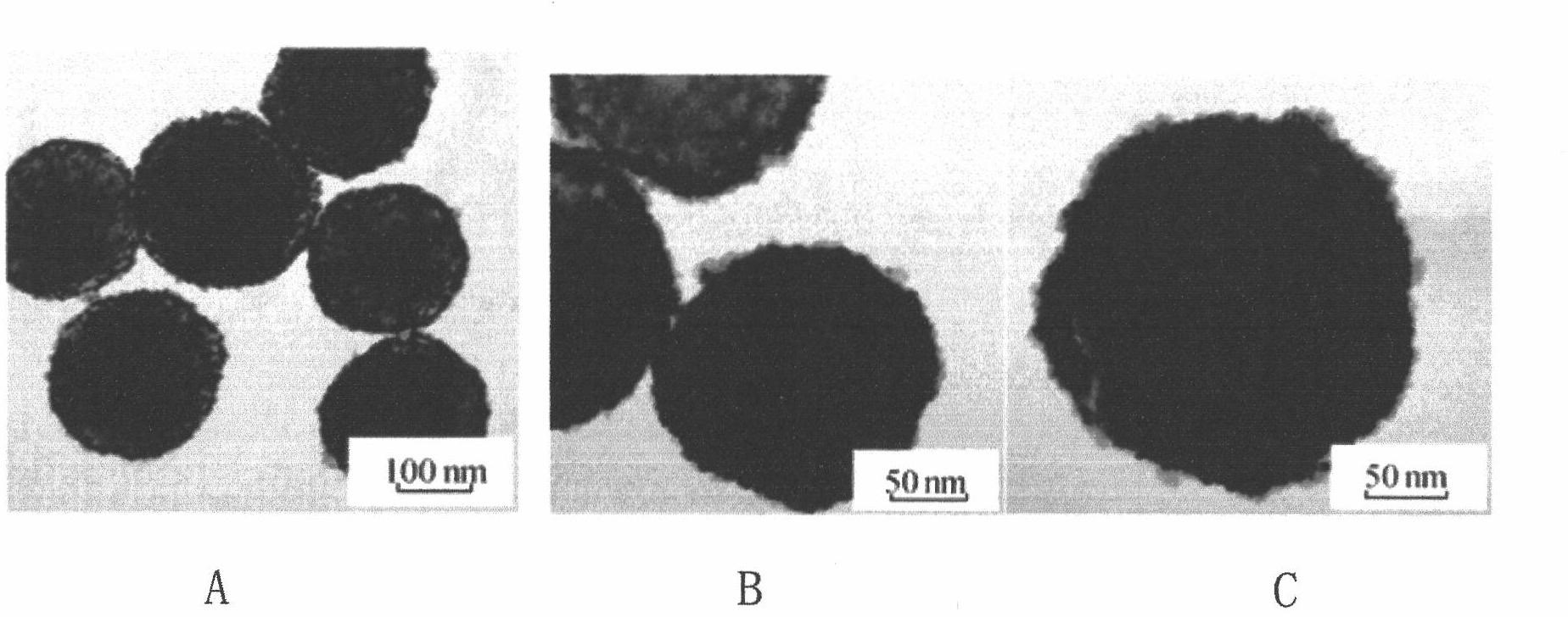
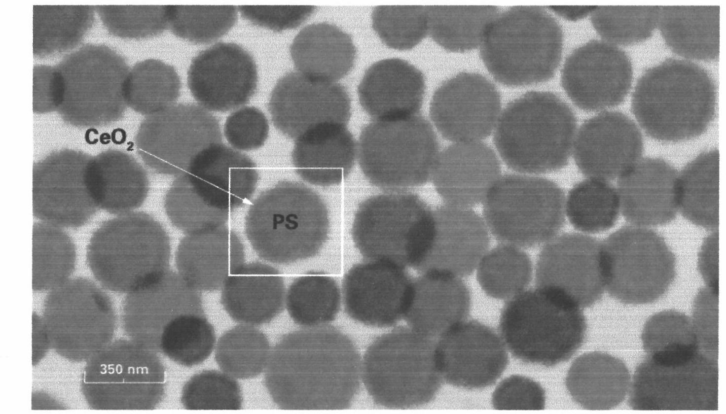
[0031] Add distilled water, a certain amount of styrene (St), an appropriate amount of divinylbenzene and α-methacrylic acid into a 250mL four-neck flask equipped with a condenser, a mechanical stirring device and a nitrogen conduit in sequence, stir well and place at a constant temperature Heat the oil bath to a certain temperature, add the initiator potassium persulfate (dissolved in 10 mL distilled water) after 10 minutes, and obtain the PS latex particle dispersion after a period of reaction. figure 1 , figure 2 with image 3 The FESEM images and TEM photos of the PS latex particle dispersion are given respectively. It can be seen from the figure that the PS latex particles in the PS latex particle dispersion are in a regular spherical shape, with a single particle size of about 400nm, clear boundaries between particles, and monodisperse Good performance, uniform particle size distribution.
[0032] Since potassium per...
Embodiment 2
[0033] Embodiment 2: Preparation of polymethacrylate / cerium oxide composite particles
[0034] Measure 4 mL of PS latex dispersion liquid and add it to 200 mL distilled water, after ultrasonic dispersion for 10 min, add a certain amount of analytically pure cerous nitrate hexahydrate (Ce(NO 3 ) 3 ·6H 2 O) and excess hexamethylenetetramine (C 6 h 12 N 4 , HMT), and control the Ce(NO 3 ) 3 ·6H 2 The molar ratio of O and HMT is 1:5. The prepared reaction solution was kept at a constant temperature of 75°C for 2 hours under the condition of electromagnetic stirring. After cooling and standing still, the precipitate was centrifuged, washed twice with distilled water and once with absolute ethanol, and then placed in a blast drying oven at 80°C to Dry to get PS / CeO 2 Composite particles.
[0035] XRD analysis of raw material and product samples, such as Figure 4 Shown are the prepared PS microspheres, pure CeO 2 and PS-CeO 2 XRD spectra of composite microspheres F1-F3....
Embodiment 3
[0036] Embodiment 3: polishing test
[0037] Weigh a certain amount of PS / CeO 2 Composite abrasive grains were prepared into polishing slurry with 0.1mol L-1 Sodium hydroxide solution was used to adjust the pH value, and then an appropriate amount of sodium hexadecylbenzenesulfonate was added as a dispersant, and ultrasonically dispersed for 15 minutes before use. Under the polishing process parameters in Table 1, an IPEC 472 precision polishing machine was used to perform a polishing test on a thermally oxidized silicon wafer (the thickness of the oxide layer was about 1.1 μm). The model of the polishing pad is TWIBP-16 (produced by Thomaswest, USA).
[0038] Table 1 Polishing experiment process parameters
[0039]
[0040]
[0041] Measure the removal rate (in A) of the silicon dioxide wafer after polishing with the oxide measuring machine FT-750, the result is as follows Figure 5-1 to Figure 5-3 shown.
[0042] Figure 6-1 with Figure 7-1 Shown are the surface...
PUM
| Property | Measurement | Unit |
|---|---|---|
| The average particle size | aaaaa | aaaaa |
Abstract
Description
Claims
Application Information