Double-stage revolving and switching method and apparatus based on independent synchronic direction-regulation

A technology of exchange device and double workpiece table, applied in the direction of exposure device, electrical components, conveyor objects, etc. in photoengraving process, can solve the problems of shortened balancing time, small moment of inertia, loss of target of laser interferometer, etc. The effect of engraving machine productivity, improving operating efficiency and shortening equilibration time

Inactive Publication Date: 2014-02-05
HARBIN INST OF TECH
View PDF10 Cites 1 Cited by
  • Summary
  • Abstract
  • Description
  • Claims
  • Application Information

AI Technical Summary

Problems solved by technology

The invention adopts a three-beat double-stage rotation switch. During the stage change process, the workpiece table does not spin, which solves the problems of the existing rotary table scheme, the phase inversion of the workpiece table, the winding of cables, and the loss of the target of the laser interferometer.
At the same time, the present invention adopts the platform changing method that the workpiece table rotates around the center of the abutment, avoids rotating the whole abutment, and solves the problems of large radius of gyration and large moment of inertia in the prior art, and the moment of inertia is small. Shorter times improve workbench operating efficiency and lithography machine productivity
The present invention also solves the problems of large impact torque and many beats in the existing linear channel change scheme, and can adopt a smaller mass balance system, which is beneficial to shorten the balance time, simplify the system at the same time, reduce costs, and shorten the cycle time of channel change. It takes less time to change the platform, which can effectively improve the productivity of the lithography machine

Method used


Image

  • Double-stage revolving and switching method and apparatus based on independent synchronic direction-regulation
  • Double-stage revolving and switching method and apparatus based on independent synchronic direction-regulation
  • Double-stage revolving and switching method and apparatus based on independent synchronic direction-regulation

Examples


Embodiment Construction

[0025] Embodiments of the present invention will be described in detail below in conjunction with the accompanying drawings.

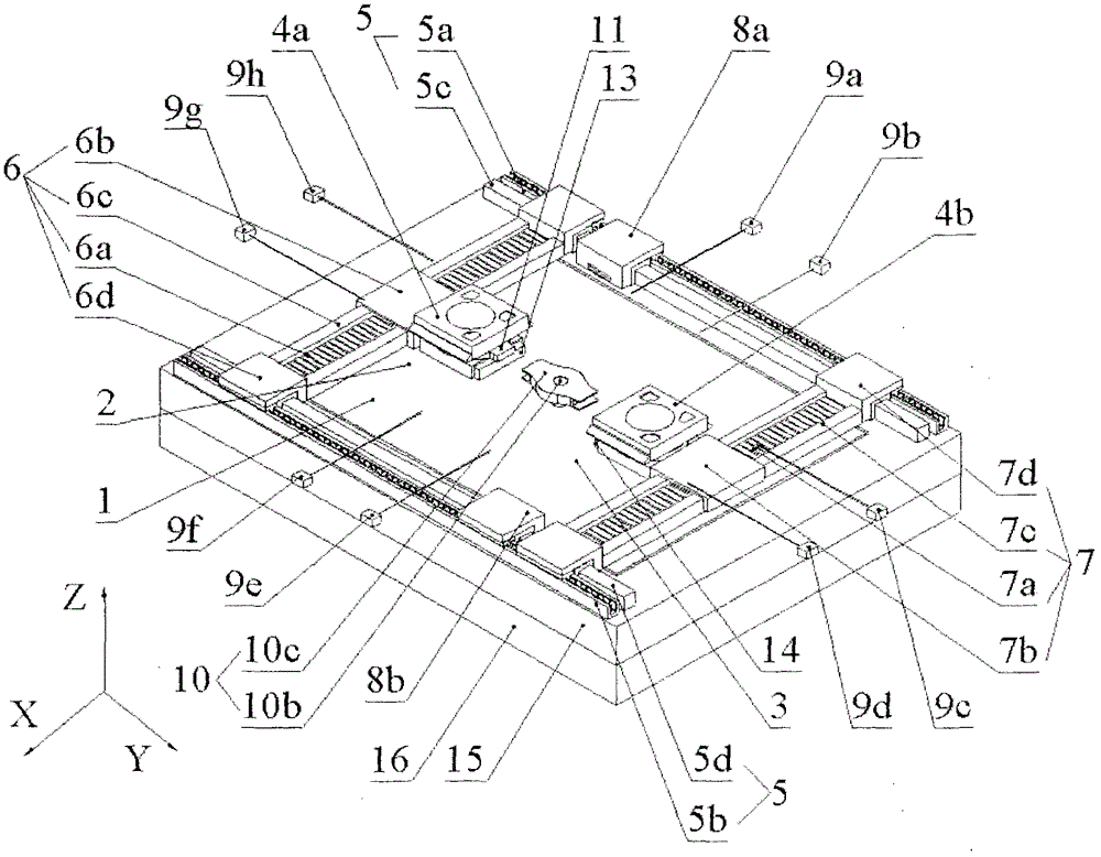
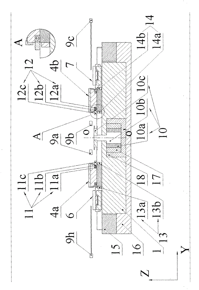
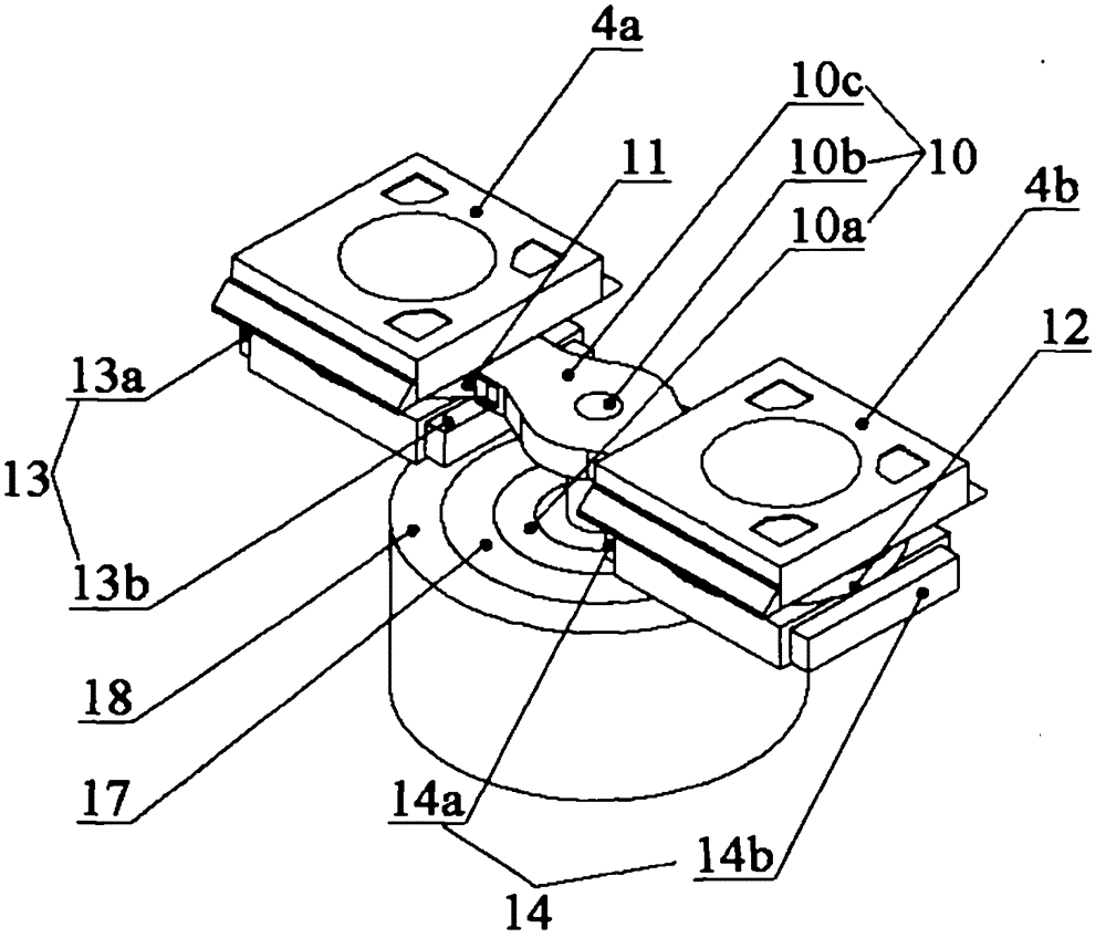
[0026] A dual-workpiece rotary exchange method based on autonomous synchronous direction adjustment, the steps of the method are as follows:

[0027] In the initial working state, the pre-alignment of the second workpiece table at the pretreatment station is completed, and the exposure of the first workpiece table at the exposure station is completed;

[0028] In the first step, the first workpiece stage after exposure is driven by the Y-direction long-stroke linear motion unit and the X-direction first long-stroke linear motion unit to the predetermined position for changing the stage, and the second workpiece stage that has been pre-aligned is also driven by the Y-direction long-stroke linear motion unit. The stroke linear motion unit and the X-direction second long-stroke linear motion unit are driven to the predetermined position for table change, ...


PUM


Abstract

The invention relates to a double-stage revolving and switching method and a double-stage revolving and switching apparatus based on independent synchronic direction-regulation. The invention belongs to semiconductor device manufacturing equipments. The apparatus comprises a revolving stage-switching apparatus formed by a revolving stage-switching motor stator, a revolving stage-switching motor mover, and a rotary joint. Spinning apparatuses are provided on working stages. The spinning apparatuses comprise spinning motor stators, spinning motor movers, and spinning motor mover switching pieces. The revolving stage-switching apparatus is connected with the spinning motor mover switching pieces, such that the working stages can be driven to rotate around the center of a base stage. Therefore, position switching can be realized. With the apparatus provided by the invention, problems of inversed phases, twisted cables, and laser interferometer target loss of existing revolving stage-switching technologies can be solved. The apparatus is advantaged in small inertia moment, short stage-switching time with a same torque condition, high working stage operation efficiency, and high mask aligner yield.

Description

technical field [0001] The invention belongs to semiconductor manufacturing equipment, and mainly relates to a method and device for rotating and exchanging double worktables based on autonomous synchronous direction adjustment. Background technique [0002] Lithography machine is one of the important ultra-precision equipment in the manufacture of very large scale integrated circuits. The resolution and engraving accuracy of the lithography machine determine the minimum line width of the integrated circuit chip. At the same time, the yield of the lithography machine greatly affects the production cost of the integrated circuit chip. As the key subsystem of the lithography machine, the workpiece table It also determines the resolution, overlay accuracy and productivity of the lithography machine to a large extent. [0003] Productivity is one of the main goals of lithography machine development. Under the condition of satisfying the resolution and overlay accuracy, improvi...

Claims


Application Information

Patent Timeline
Patent Type & Authority Patents(China)
IPC IPC(8): G03F7/20H01L21/67H01L21/677
Inventor 谭久彬杨远源王雷
Owner HARBIN INST OF TECH
Why Eureka
Try Eureka