Sensorless controller of bearingless synchronous reluctance motor and method for controlling sensorless controller

A synchronous reluctance motor and controller technology, applied in the direction of speed/torque control of a single motor, can solve the problems of weakening random interference and measurement noise, lack of parameter configuration, poor identification accuracy, etc., achieving excellent robustness, good Anti-interference performance, low loss effect

Active Publication Date: 2012-06-20
江阴智产汇知识产权运营有限公司
View PDF6 Cites 12 Cited by
  • Summary
  • Abstract
  • Description
  • Claims
  • Application Information

AI Technical Summary

Problems solved by technology

The back electromotive force method is simple, but largely depends on the accuracy of the parameters; the model reference adaptive method based on voltage and current has a pure integral link, the identification accuracy is poor, and is affected by the stator resistance, and it is unstable at low speed; The model reference adaptive method of electric potential can solve the pure integral problem, but the identification error is large when the speed crosses zero; the model reference adaptive method based on the instantaneous reactive power model is not affected by the stator resistance, but the speed is not affected when the speed is given as a negative step. Stable; the extended Kalman filter method uses the minimum variance optimal prediction and estimation method to weaken random interference and measurement noise, but the algorithm is complex, the parameter configuration lacks certain standards, and the amount of calculation is large; the high-frequency harmonic signal injection method estimates the speed, which can Improve its low-speed performance, but it is greatly affected by the motor load

Method used


Image

  • Sensorless controller of bearingless synchronous reluctance motor and method for controlling sensorless controller
  • Sensorless controller of bearingless synchronous reluctance motor and method for controlling sensorless controller
  • Sensorless controller of bearingless synchronous reluctance motor and method for controlling sensorless controller

Examples


Embodiment Construction

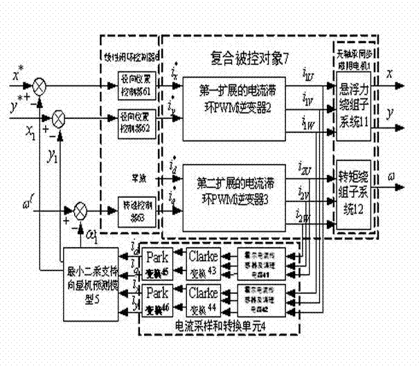
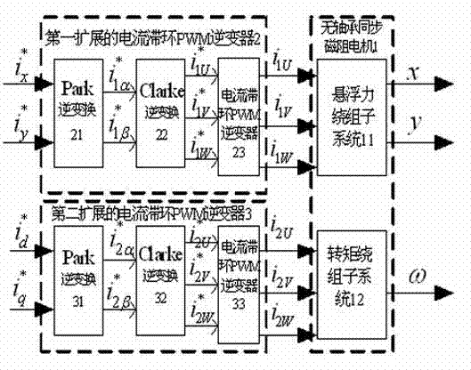
[0021] Such as figure 1 As shown, the sensorless controller of the bearingless synchronous reluctance motor of the present invention consists of a current sampling and conversion unit 4, a least squares support vector machine prediction model 5, a linear closed-loop controller 6 and parallel first and second extended current hysteresis The ring PWM inverters 2 and 3 are jointly formed, wherein the linear closed-loop controller 6 is composed of a rotational speed controller 63 and two radial position controllers 61 and 62, and the two radial position controllers 61 and 62 are respectively connected in series It is connected before the first extended current hysteresis PWM inverter 2 , and one speed controller 63 is connected in series before the second extended current hysteresis PWM inverter 3 . The first and second two extended current hysteresis PWM inverters 2, 3 and the bearingless synchronous reluctance motor 1 together form a composite controlled object 7; the bearingle...


PUM


Abstract

The invention discloses a sensorless controller of a bearingless synchronous reluctance motor and a method for controlling the sensorless controller. The sensorless controller consists of a current sampling and conversion unit, a least square support vector machine prediction model, a linear closed-loop controller, and two expanded current hysteresis pulse width modulation (PWM) inverters which are connected in parallel, wherein the current sampling and conversion unit acquires an output current and generates an input current of the least square support vector machine prediction model; the least square support vector machine prediction model respectively compares prediction radial displacement and a rotary speed, which are output, with given reference values to obtain difference values which serve as input signals of the linear closed-loop controller; and control current components of a suspension force winding and a torque winding which are generated by the linear closed-loop controller are input into the two current hysteresis PWM inverters to respectively generate the input currents of a system. By the invention, the bearingless synchronous reluctance motor can be steadily suspended in a sensorless mode in a full-speed range, and high anti-interference performance and high robustness are realized.

Description

technical field [0001] The invention belongs to the technical field of electric drive control equipment, and relates to a sensorless controller of a bearingless synchronous reluctance motor and a control method thereof, which perform high-performance stable control on the sensorless operation of the bearingless synchronous reluctance motor. Background technique [0002] The bearingless synchronous reluctance motor can meet the requirements of modern industry for high-speed, non-lubricated, friction-free, and maintenance-free high-performance drive motors. It is a new type of synchronous reluctance motor with both excellent performance of magnetic bearings motor. Compared with the traditional bearingless motor, the bearingless synchronous reluctance motor has many advantages: the permanent magnet is omitted on the rotor, and there is no excitation winding, the structure is simple, the operation is reliable, the cost is low, and because it can achieve a high salient pole ratio...

Claims


Application Information

Patent Timeline
Patent Type & Authority Applications(China)
IPC IPC(8): H02P6/08
Inventor 朱熀秋李衍超刁小燕李天博张涛
Owner 江阴智产汇知识产权运营有限公司
Why Eureka
Try Eureka