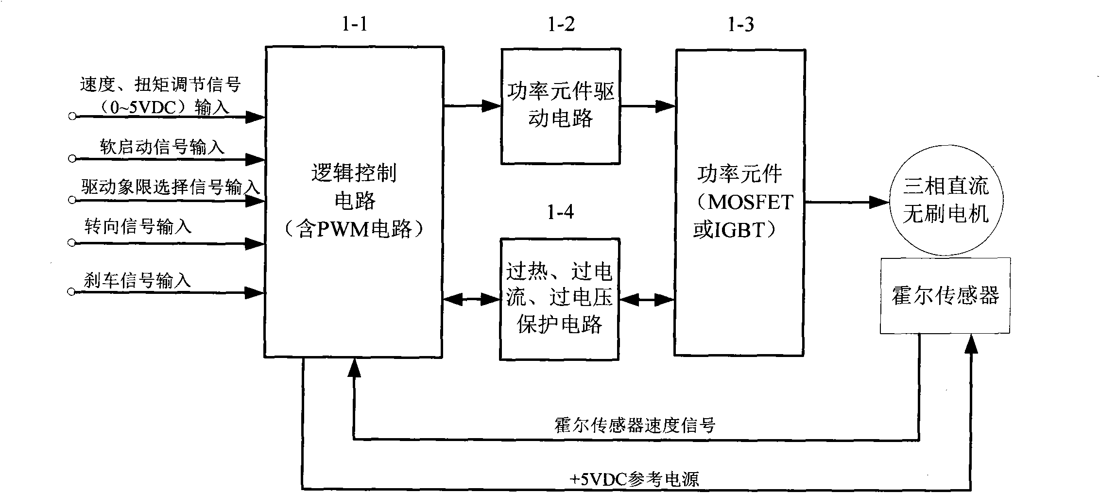
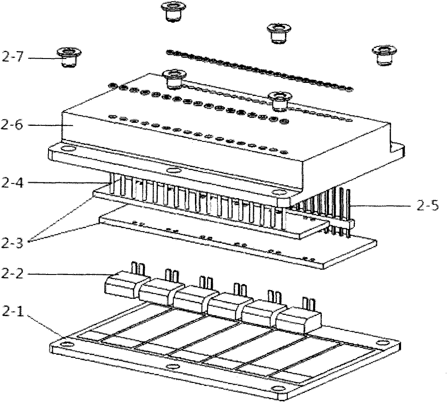
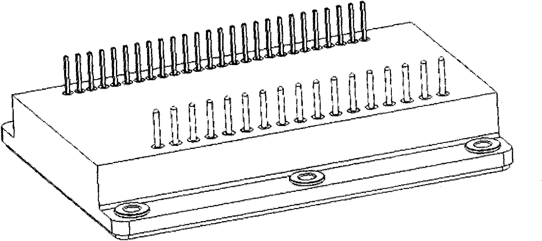
High-power three-phase brushless direct-current motor control module and packaging of control module
A brushless DC motor, high-power technology, applied in the direction of a single motor speed/torque control, circuit device, emergency protection circuit device, etc., can solve the problems of heavy weight, short service life, large volume, etc., and achieve simple and flexible use. , compact and powerful effects
- Summary
- Abstract
- Description
- Claims
- Application Information
AI Technical Summary
Problems solved by technology
Method used
Image
Examples
Embodiment 1
[0066] Embodiment 1: Voltage Control Mode
[0067] Figure 4 It is a typical voltage (speed) control wiring diagram. A voltage command proportional to the required speed is input to pin 4, this signal can be adjusted by rheostat R3. The speed feedback signal is obtained by filtering the output signal of Tach-out (pin 15) through the low-pass filter circuit R1 and C1. An internal fault-tolerant amplifier compensates for small signals in the speed control loop. The output of the fault-tolerant amplifier is connected to the PWM comparator. Because the motor speed is directly proportional to the average phase voltage, the speed control is actually controlled by the pulse width ratio. If open-loop speed control is used, pin 2 should be shorted with pin 8.
[0068] The loop-by-loop current limit function is implemented by connecting pins 25, 26, 12, and 13. The overcurrent protection limit is set by overcurrent reference pin 9. This reference is internally set to 1.15V, but c...
Embodiment 2
[0069] Embodiment 2: Current Control Mode
[0070] Figure 5 It is a typical current (torque) control connection diagram. A voltage command proportional to the required current is input to pin 4, and this signal can be adjusted by rheostat R3. The current feedback signal (Pin 11) is obtained through an internal current sensor and amplifier. The output of the internal fault-tolerant amplifier is connected to the PWM comparator. Because the torque is directly proportional to the average phase current, the torque control is actually controlled by the pulse width ratio.
[0071] The set value of the overcurrent protection reference pin 9 should be slightly higher than the maximum control current, which can ensure that the loop-by-loop current limit function of the module can still function when there is a large signal disturbance that causes the fault-tolerant amplifier to saturate.
Embodiment 3
[0072] Embodiment 3: DC bus filtering
[0073] In order to reduce the influence of parasitic inductance in the circuit during operation, the module motor connection circuit should be in accordance with Figure 6 connect. Capacitors C1, C2 and C3 can be ceramic capacitors from 0.1uF to 0.5uF. The electrolytic capacitor C4 is connected to the DC bus, and the capacitance of C4 is calculated according to the ratio of 10uF / A.
[0074] Below, a specific embodiment of a motor control module with a current of 20A and a voltage of 600V is given in combination with the above-mentioned embodiments:
[0075] 1. Setting conditions:
[0076] 1. PWM peak value 7.5V (5±2.5V).
[0077] 2. The fault-tolerant amplifier output (pin 8) is internally connected to the PWM comparator.
[0078] 3. Depending on the motor resistance and the power supply voltage, the output of the fault-tolerant amplifier should be less than 7.5V under normal operating conditions.
[0079] 4. The output of the faul...
PUM
 Abstract
Description
Claims
Application Information
 - R&D
- Intellectual Property
- Life Sciences
- Materials
- Tech Scout
- Unparalleled Data Quality
- Higher Quality Content
- 60% Fewer Hallucinations
Browse by: Latest US Patents, China's latest patents, Technical Efficacy Thesaurus, Application Domain, Technology Topic, Popular Technical Reports.
© 2025 PatSnap. All rights reserved.Legal|Privacy policy|Modern Slavery Act Transparency Statement|Sitemap|About US| Contact US: help@patsnap.com


