

Process for producing reduced iron powder
A technology for reducing iron powder and production technology, which is applied in the direction of fluidized bed furnace, etc., can solve the problems of slow reduction speed, large waste heat value, and low production efficiency, and achieve the effect of fast reduction speed, short time consumption and high production efficiency
- Summary
- Abstract
- Description
- Claims
- Application Information
AI Technical Summary
Problems solved by technology
Method used
Image

Examples
Embodiment 1
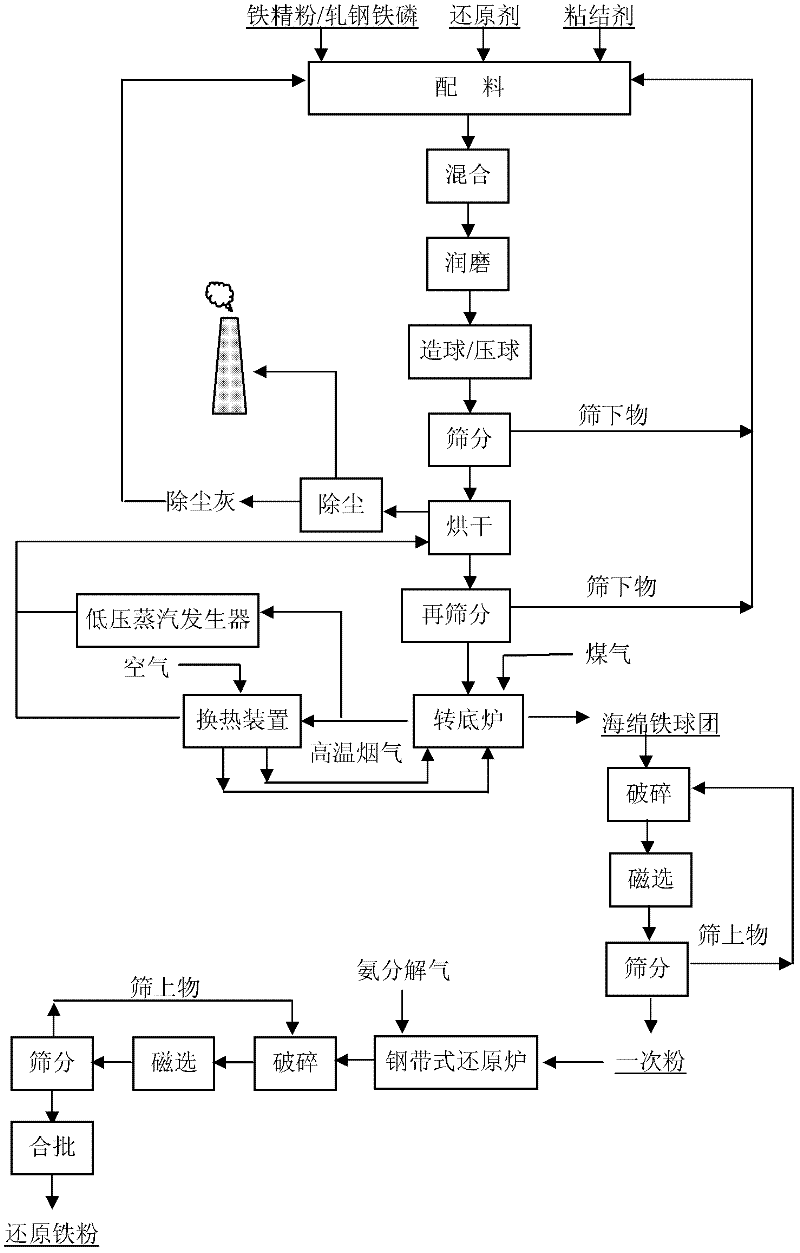
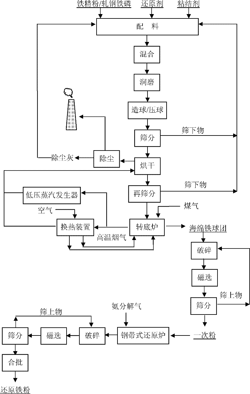
[0033] High-purity iron fine powder with a TFe content of 73.2%, coke powder, and organic binder are used for mixing according to the mass ratio of 80.9:16.3:2.8. The water content of the mixture is controlled at about 9%. The disc pelletizer is used to produce Φ20mm-Φ30mm raw materials. Balls; raw balls are dried with hot air at 300°C in a chain grate dryer for 15 minutes to remove moisture to less than 3%; then put into a rotary hearth furnace for reduction, and undergo five-stage reduction (maximum reduction temperature 1250°C) for 30 minutes to obtain Sponge iron with a TFe content of more than 95%; the sponge iron is crushed, magnetically separated, and sieved, and the -200um primary powder is fed into a steel belt reduction furnace, and reduced at 920°C for 40-60min in an ammonia decomposition atmosphere to obtain a powder cake; The powder cake is crushed, screened, and batched together to produce high-quality reduced iron powder with a particle size of -150um ≥ 95, TFe ≥...
Embodiment 2
[0035] Use high-purity iron fine powder with a TFe content of 73.2%, coal powder, and organic binder for mixing at a mass ratio of 80.9:16.3:2.8. The water content of the mixture is controlled at about 8%. A high-pressure ball pressing machine is used to make 20×30×40mm briquette; the briquette is dried in a chain grate dryer at 250°C for 20 minutes with hot air, and the water content is removed to below 3%; then it is sent to a rotary hearth furnace for reduction and undergoes five-stage reduction (maximum reduction temperature 1320°C) for 28 minutes , to obtain sponge iron with a TFe content of more than 95%; after the sponge iron is crushed, magnetically separated, and screened, the -200um primary powder is fed into a steel belt reduction furnace, and reduced at 920°C for 50-70min under an ammonia decomposition atmosphere to obtain Powder cake: The powder cake is crushed, sieved, and batched together to produce high-quality reduced iron powder with a particle size of -150um≥...
example 3
[0037] Using TFe content of 73.5% rolled iron and steel, phosphorus, coal powder, and organic binder are mixed according to the mass ratio of 81.0:16.2:2.8, and the water content of the mixture is controlled at about 9%. The disk pelletizing machine is used to produce Φ25mm-Φ35mm raw materials. Balls; the raw balls are dried in a chain grate dryer with hot air at 260°C for 18 minutes, and the water content is removed to below 3%; then they are reduced in a rotary hearth furnace, and undergo five-stage reduction (maximum reduction temperature 1320°C) for 28 minutes to obtain Sponge iron with a TFe content of more than 95%; the sponge iron is crushed, magnetically separated, and sieved, and the -200um primary powder is fed into a steel belt reduction furnace, and reduced at 920°C for 50-60min in an ammonia decomposition atmosphere to obtain a powder cake; The powder cake is crushed, screened, and batched together to produce high-quality reduced iron powder with a particle size of...
PUM
 Abstract
Description
Claims
Application Information