Combination method and device of caustic sludge desulfuration and dephenolization neutralization and tail gas desulphurization processing

A combined method and combined device technology, which is applied in the fields of desulfurization of oil desulfurization alkali slag, neutralization and tail gas desulfurization, and dephenolization. It can solve the problems of equipment and pipeline corrosion, insufficient oxidation capacity, and inability to directly discharge, etc., and achieve the best results Good results

Active Publication Date: 2012-09-19
CHINA PETROLEUM & CHEM CORP +1
View PDF8 Cites 16 Cited by
  • Summary
  • Abstract
  • Description
  • Claims
  • Application Information

AI Technical Summary

Problems solved by technology

But for the alkali slag whose sodium sulfide and sodium mercaptide content exceeds 5%wt, the oxidation ability is still insufficient; at the same time, the oxidation tail gas of the alkali slag contains 10000mg / m 3 The above disulfides have a foul smell and slight toxicity and cannot be discharged directly. They can only be sent to incineration. However, disulfides will generate sulfur dioxide during incineration, which will seriously corrode equipment and pipelines. If the sulfur dioxide generated is not desulfurized processing, seriously polluting the environment

Method used


Image

  • Combination method and device of caustic sludge desulfuration and dephenolization neutralization and tail gas desulphurization processing
  • Combination method and device of caustic sludge desulfuration and dephenolization neutralization and tail gas desulphurization processing
  • Combination method and device of caustic sludge desulfuration and dephenolization neutralization and tail gas desulphurization processing

Examples


example

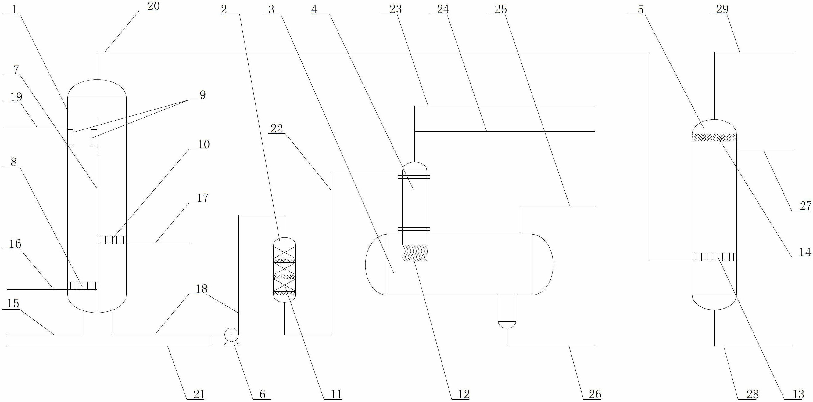
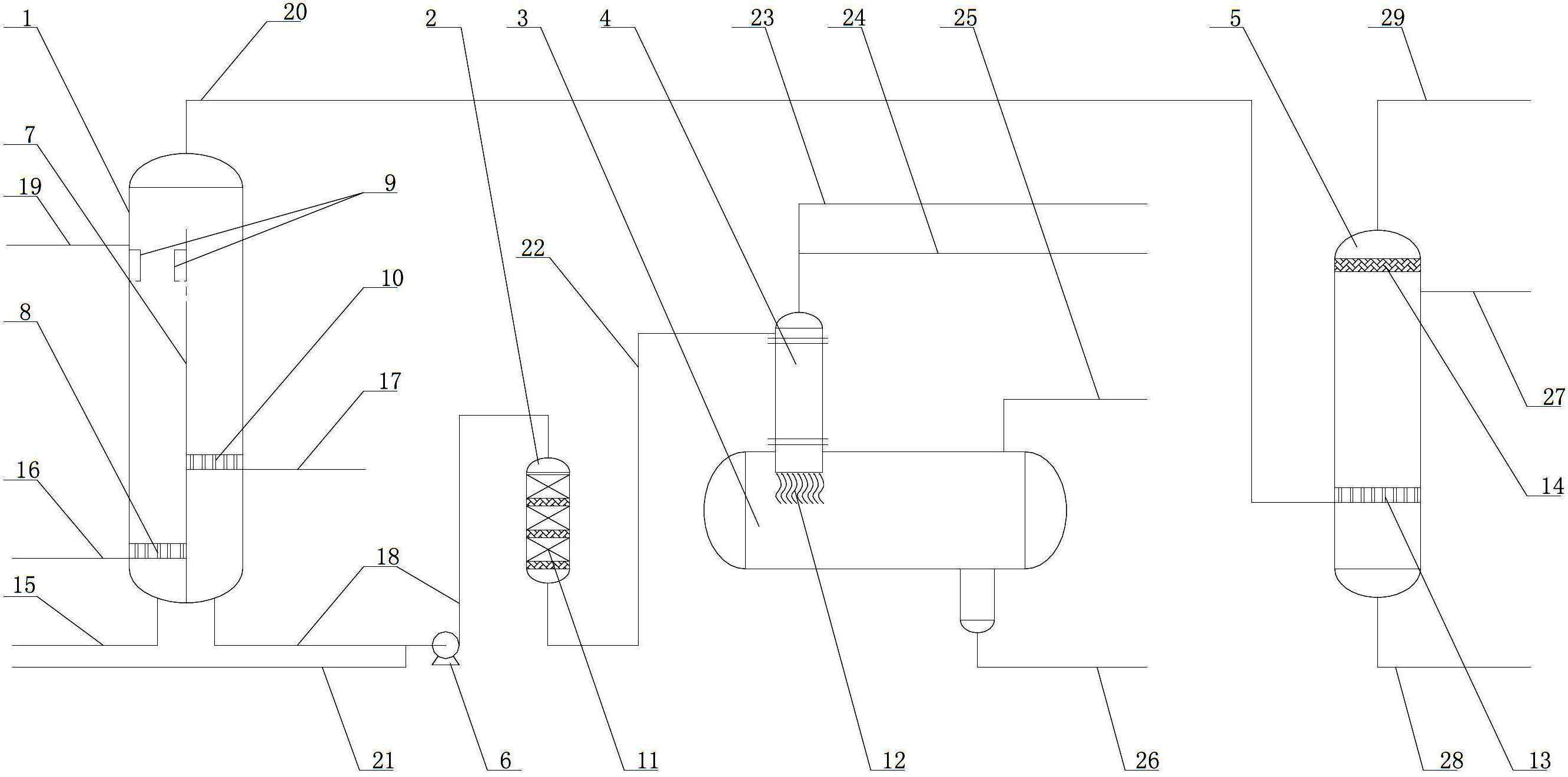
[0048] A Sinopec company adopts the combination method of the present invention to build a set of gasoline desulfurization pre-alkali washing alkali slag industrial device: alkali slag processing capacity: 400Kg / h; alkali slag composition: sodium hydroxide concentration 6-10%wt, sodium sulfide and Sodium mercaptide concentration 5-6.5%wt, sodium phenate content 3-5%wt, COD23-300,000 mg / L; main equipment specifications: alkali slag oxidation desulfurization tower Φ1400×9000, alkali slag filter Φ600×1200, fiber liquid Membrane contactor Φ400×4000, alkali slag carbonization separation tank Φ2000×7000, tail gas adsorption desulfurization tank Φ800×3100; process operation parameters: alkali slag preheating temperature 25-30 ℃, adding solid catalyst 1Kg per day, oxidation air flow 100-130Nm3 / h, fresh water flow rate 400-800Kg / h, gasoline flow rate 5000-8000Kg / h, carbon dioxide flow rate 25-40 Nm3 / h; device operation results: disulfide content in tail gas <200mg / m3 (calculated as dis...


PUM


Abstract

The invention relates to a combination method and a device of caustic sludge desulfuration and dephenolization neutralization and tail gas desulphurization processing. The device comprises a caustic sludge oxidation desulfurization tower, a caustic sludge filter, a carbonization precipitation tank, a fiber liquid membrane contactor and a tail gas adsorption desulfurization tank, the top of the caustic sludge oxidation desulfurization tower is connected with a tail gas adsorption desulfurization tank through a tail gas discharging pipe one, the bottom of the caustic sludge oxidation desulfurization tower is connected with the caustic sludge filter through a caustic sludge discharging pipe, the caustic sludge filter is connected with the fiber liquid membrane contactor through a caustic sludge feeding pipe two, and the bottom of the fiber liquid membrane contactor is fixed on the carbonization precipitation tank through a flange; and the method includes subjecting the caustic sludge to oxidation treatment, air stripping fine taking off disulphide treatment and removing mechanical impurities ad colloids, separating hydrogen sulfide and mercaptan and adsorption desulfurization treatment successively. The combination method and the device of caustic sludge desulfuration and dephenolization neutralization and tail gas desulphurization processing have the advantages that disulphide of sodium sulphide and mercaptan sodium can be separated and recycled, and the tail gas after desulfuration can meet the relevant state standard requirements of direct discharge.

Description

technical field [0001] The invention relates to a combined method and device for alkali residue treatment and tail gas treatment, in particular to a combined method and device for oil desulfurization alkali residue desulfurization, phenol removal, neutralization and tail gas desulfurization. Background technique [0002] Gasoline, naphtha, aromatics, liquefied petroleum gas, etc. produced by refineries contain sulfur-containing impurities such as hydrogen sulfide and mercaptans. Each refinery has a large amount of alkali slag discharge. The alkali slag contains sodium hydroxide, sodium sulfide, sodium mercaptide, sodium phenate and trace light hydrocarbons. Its pH value is above 14 and its COD is as high as 200,000-600,000 mg / L. Toxic substances and foul smell cannot be sent to biochemical ponds for treatment, nor can they be sent to sewage treatment plants, otherwise it will seriously affect the normal operation of sewage treatment and affect the health of staff. [0003]...

Claims


Application Information

Patent Timeline
Patent Type & Authority Applications(China)
IPC IPC(8): B09B1/00B09B5/00
Inventor 刘家海余伟聂通元刘百强喻武钢刘学东王铭王伟陈华陈兴肖楠罗伟军
Owner CHINA PETROLEUM & CHEM CORP
Why Eureka
Try Eureka