
Sludge dewatering and granulating device and method with synergic effect of annular electric field and pressure

A synergistic and sludge dewatering technology, which is applied in the direction of raw material extrusion granulation, dehydration/drying/thickened sludge treatment, etc., can solve the problems of large impact of water penetration and removal, uneven pressure distribution, and difficulty in realizing particle shape, etc. problems, achieve the effects of reducing water movement resistance, uniform pressure distribution, and reducing costs

Inactive Publication Date: 2012-09-19
TIANJIN UNIV
View PDF5 Cites 0 Cited by
  • Summary
  • Abstract
  • Description
  • Claims
  • Application Information

AI Technical Summary

Problems solved by technology

Electric dehydration technology has been proposed long ago, but it is mostly limited to laboratory research, and there are few industrial application equipment. The difficulty in its application is mainly the form of electric field and the combination with mechanical pressure. At present, the electric field used is mostly double-drum electric field and non-fixed plate type. parallel electric field
In application, the double-drum electric field has the problems of short electric dehydration time and low dehydration efficiency, while the non-fixed plate parallel electric field has problems such as poor electric field stability and uneven pressure distribution.
[0007] In the current electric dehydration method, there are still the following problems that are difficult to overcome: (1) mechanical pressure is applied indirectly to the sludge through a roller or a non-fixed plate electrode, and there are uneven pressure distribution, dry spots and liquid phase discontinuity (2) In order to facilitate feeding and prevent electric field short circuit, thicker filter cloth is usually used, which has a greater impact on water penetration and removal; (3) It does not have the function of granulation, and the sludge after electric dehydration is not good. Regular flakes, it is difficult to achieve other particle shapes that are specially required for subsequent processing
[0008] In addition, the fixed plate-shaped parallel electric field dehydration and granulation method has a good effect on solving the above problems, but in the application, the resistance of the fixed plate-shaped electric field to the sludge is relatively large, and it is difficult to connect with the existing sludge pressurized preparation, and mechanical pressure Serious deformation of electrodes in the back electric field
[0009] In view of the above problems, the operation stability and reliability of electric dehydration equipment have declined, which greatly restricts the application of this technology

Method used


Image

  • Sludge dewatering and granulating device and method with synergic effect of annular electric field and pressure
  • Sludge dewatering and granulating device and method with synergic effect of annular electric field and pressure
  • Sludge dewatering and granulating device and method with synergic effect of annular electric field and pressure

Examples


Embodiment 1

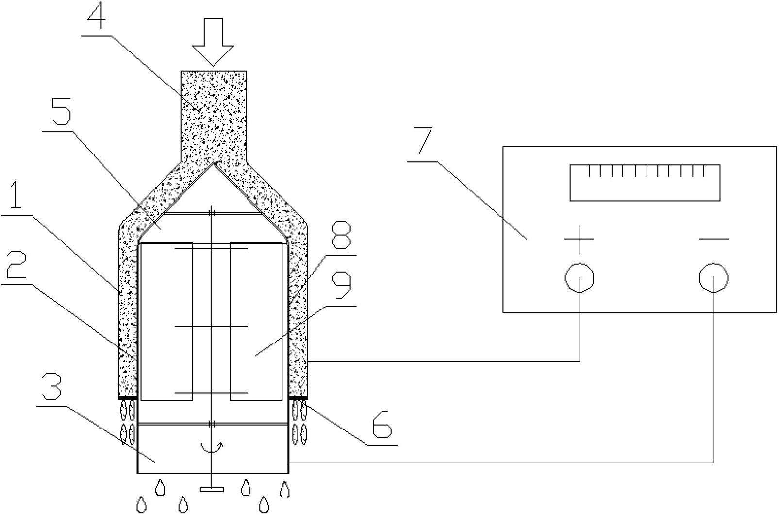
[0030] Such as figure 1 As shown, the metal cylinder anode 1 and the mesh cylinder cathode 3 are concentrically arranged in a sleeve with a distance of 5mm, and are connected to the positive and negative poles of the DC power supply 7 respectively. A filter cloth 8 is laid between the mesh cathode 3 and the sludge 2 . The dewatered sludge 2 with a moisture content of 85% is injected from the mud inlet 4 after being pressurized at 100,000 Pa, diverted by the conical baffle plate 5 with a conical apex angle of 60°, and then enters the annular electric field. The outlet moves, and the water in the sludge passes through the filter cloth 8 and the cathode 3 and is scraped off by the scraper 9 to complete the dehydration process. The dehydrated sludge is extruded into granules by the granulation baffle 6 and then discharged. The shape of the sludge discharge port is circular, and the opening rate is 50%. The DC power supply adopts a continuous voltage regulation method, and the po...

Embodiment 2

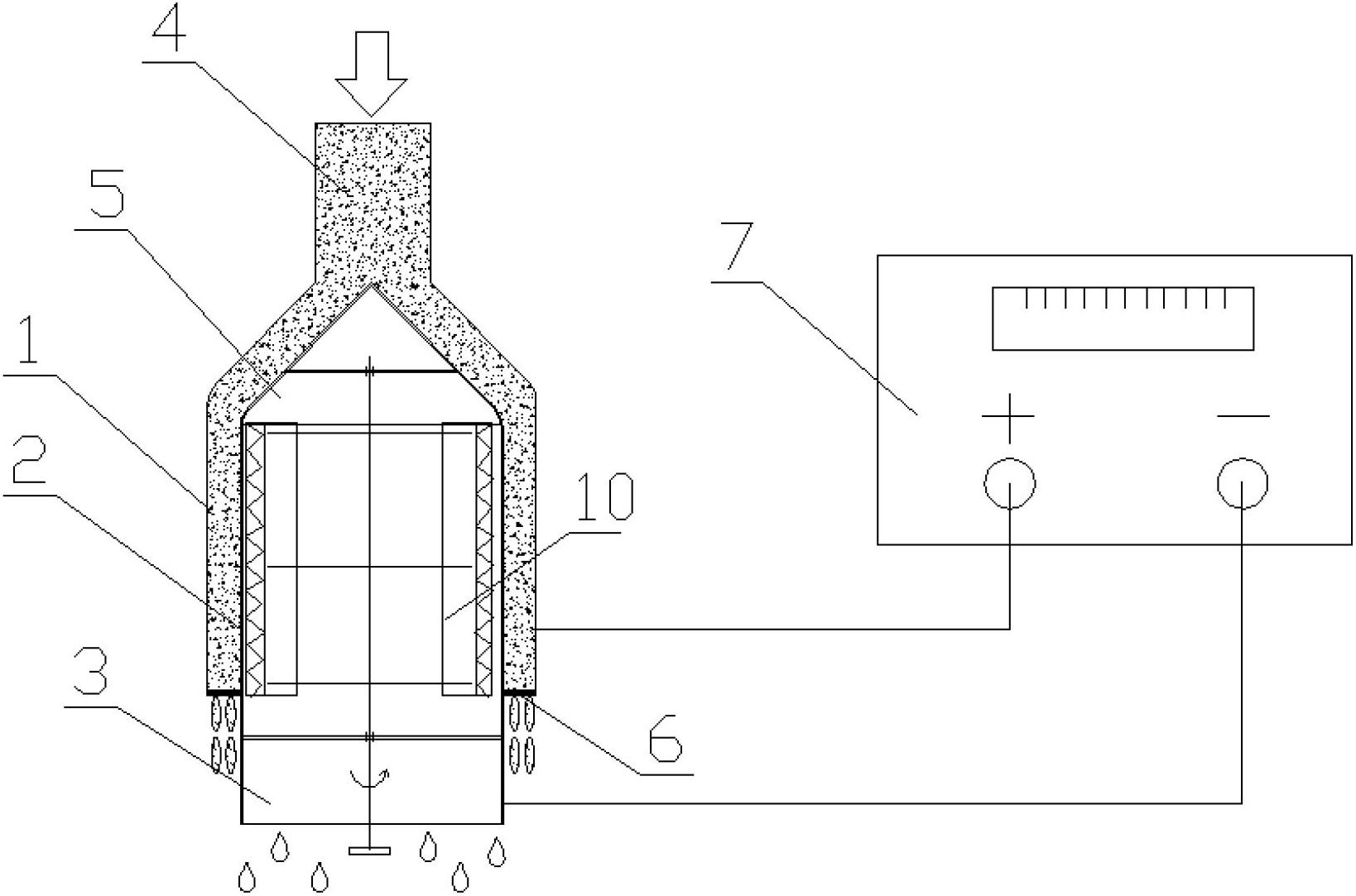
[0032] Such as figure 2 As shown, the metal cylinder anode 1 and the mesh cylinder cathode 3 are concentrically arranged as a sleeve with a distance of 2 mm, and are respectively connected to the positive and negative poles of the DC power supply 7 . Mesh cathode 3 itself has filtering function. The dewatered sludge 2 with a water content of 90% is injected from the mud inlet 4 after being pressurized at 1000 Pa, diverted by the conical baffle plate 5 with a conical apex angle of 60°, and then enters the annular electric field. The outlet moves, and the moisture in the sludge passes through the cathode 3 and is brushed away by the brush 10 to complete the dehydration process. The dehydrated sludge is extruded into granules by the granulation baffle 6 and then discharged. The shape of the sludge discharge port is oval, and the opening ratio is 80%. The DC power supply adopts a continuous voltage regulation method, and the power supply voltage is 10V. After the sludge is deh...

Embodiment 3

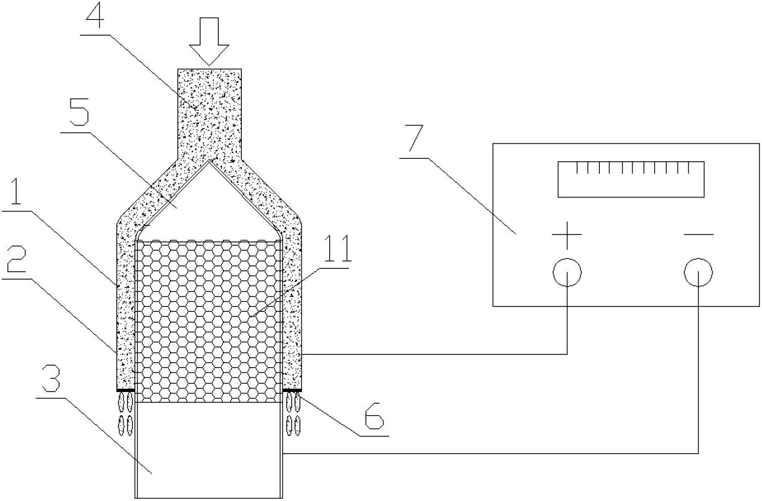
[0034] Such as image 3 As shown, the metal cylinder anode 1 and the mesh cylinder cathode 3 are concentrically arranged in a sleeve with a distance of 20 mm, and are respectively connected to the positive and negative poles of the DC power supply 7 . Mesh cathode 3 itself has filtering function. The dewatered sludge 2 with a moisture content of 50% is injected from the mud inlet 4 after being pressurized at 300,000 Pa, diverted by the conical baffle plate 5 with a conical apex angle of 120°, and then enters the annular electric field. The outlet moves, and the moisture in the sludge passes through the cathode 3 and is separated by the water-absorbing material 11 to complete the dehydration process. The dehydrated sludge is extruded into granules by the granulation baffle 6 and then discharged. The shape of the sludge discharge port is square and the opening ratio is 30%. The DC power supply adopts the pulse power supply mode, the power supply voltage is 150-200V, and the po...


PUM


Abstract

The invention relates to a sludge dewatering and granulating device and method with a synergic effect of an annular electric field and a pressure. According to the device, a dewatering cavity is commonly formed by a sludge inlet, a sleeve electrode, a flow-splitting separation plate and a granulating separation plate, which are concentrically arranged; the sleeve electrode is formed by concentrically arranging two cylinders; an outer side cylinder is an anode and is connected with a direct-current power supply anode; an inner-side cylinder is net-shaped and is connected with a power supply cathode to be used as an electric field cathode; the two electrodes are arranged into the annular electric field in an insulating manner; a cone separation plate is arranged at a sludge feeding section of the inner-side cylinder, the diameter of the cone separation plate is the same as that of the inner-side cylinder and the cone vertex angle is 60-120 degrees; the granulating separation plate is arranged at a sludge outlet; an opening is arranged on the granulating separation plate to be used as a sludge discharging opening and the aperture ratio is 30-80%; a mechanical pressure directly acts on the sludge when the sludge is fed and is in a range of 1000-300000 Pa; and the voltage of a dewatering electric field is 10-200 V. The method solves the problem of the traditional mechanical dewatering manner that the dewatering rate is low, surplus water of the sludge can be rapidly and efficiently removed, and a granulating function is realized, so that the method is good for reducing the sludge.

Description

technical field [0001] The invention belongs to a sludge dehydration and granulation device, in particular to a sludge dehydration and granulation device and method in which an annular electric field and pressure cooperate. Background technique [0002] Sludge includes urban sewage plant sludge, water supply plant sludge, drainage ditch sludge, water dredging sludge, etc. The amount is much larger than the amount of urban domestic waste, and urban sludge contains high pollutant content. Among them, the content of organic matter in the residual sludge of urban sewage plants is 10 times that of urban sewage, and the content of pathogenic microorganisms in dewatered sludge cakes of sewage plants is several orders of magnitude higher than that of municipal solid waste. In addition, all kinds of sludge may also contain heavy metals, highly toxic organic substances and other pollutants. Therefore, the harm that municipal sludge may cause to the environment is serious. [0003] S...

Claims


Application Information

Patent Timeline
IPC IPC(8): C02F11/12B01J2/20
Inventor 马德刚赵娴
Owner TIANJIN UNIV
Learn More