
Divide-by-four injection locked frequency divider circuit with low power consumption and wide lock range

A technology of injecting locking and locking range, which is applied in the direction of automatic power control and electrical components, and can solve problems such as small locking range, increased power consumption and area of ​​frequency divider links, and small output swing of the front stage.

Inactive Publication Date: 2012-10-03
FUDAN UNIV
View PDF4 Cites 4 Cited by
  • Summary
  • Abstract
  • Description
  • Claims
  • Application Information

AI Technical Summary

Problems solved by technology

At present, the injection-locked frequency divider architecture with a high frequency division ratio mainly adopts a single resonant circuit frequency divider, and there are many frequency dividers except three and four, but it is difficult for a single resonant circuit to generate harmonic components with a high frequency division ratio, so Very limited range of locks
However, the output swing of the front stage of the cascaded high-division ratio injection-locked divider is small, and the second harmonic component is large, which makes it more difficult for the latter stage to achieve a wide locking range. Therefore, except for the locking range of the four-injection-locked divider Much smaller locking range than divide-by-two injection-locked dividers
If a filter phase-adjusting amplifier circuit is inserted between stages, it will inevitably increase the power consumption and area of ​​the entire frequency divider chain

Method used


Image

  • Divide-by-four injection locked frequency divider circuit with low power consumption and wide lock range
  • Divide-by-four injection locked frequency divider circuit with low power consumption and wide lock range
  • Divide-by-four injection locked frequency divider circuit with low power consumption and wide lock range

Examples


Embodiment Construction

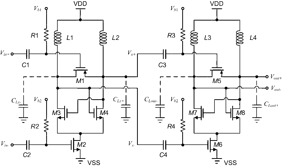
[0037] Take the design of a low-power, wide-locked-range divider-by-four injection-locked divider with an input frequency between 26.25GHz and 30.25GHz as an example.

[0038] design circuit figure 2 As shown, add a fully differential amplifier as a load circuit. The TSMC 0.13μm RF CMOS 1P8M process is adopted, the simulation tool is Cadence SpectreRF, and the power supply voltage is 800mV. where V b1 = V b3 = 1.2V, V b2 and V b4 Change to current mirror bias to reduce process deviation, the actual value is around 600mV.

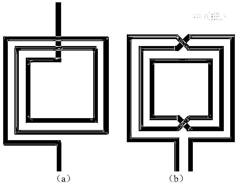
[0039] The MOS tubes are all radio frequency NMOS tubes, the resistors are high-resistance polysilicon resistors, the capacitors are MIM capacitors, the inductors are on-chip spiral inductors with center taps, and the eighth layer of metal wiring. L1 and L2 are implemented with a 1.67nH inductor, and L3 and L4 are implemented with a 4.15nH inductor.

[0040] When the input signal size is 0dBm (single-ended peak-to-peak value is 632mV) differential...


PUM


Abstract

The invention belongs to the technical field of integrated circuits and particularly discloses a divide-by-four injection locked frequency divider circuit with low power consumption and wide lock range. The divide-by-four injection locked frequency divider circuit is composed of two stages of divide-by-two injection locked frequency dividers with identical structures, circuit stages are coupled by adopting a capacitor, and each circuit stage is composed of an inductor, a crossed coupling pipe, two injection pipes, a coupling capacitor and a biasing circuit. For the structure of the circuit, two injection manners including a direct injection manner and a tail current source injection manner are adopted at the same time, so that the circuit has the advantages of the two injection manners simultaneously, injection signals are inversion signals, an injection end is a grid electrode of an MOS (Metal Oxide Semiconductor) tube, and the divide-by-two injection locked frequency dividers can be directly cascaded. The circuit disclosed by the invention can be powered by dual-power-supply voltage, is suitable for a low power supply voltage environment, is low in direct-current power consumption and can be used to realize a wider lock range. The circuit is of a differential structure and can be realized by using CMOS (Complementary Metal Oxide Semiconductor), BiMOS (Bi-state Metal Oxide Semiconductor) and other processes.

Description

technical field [0001] The invention belongs to the technical field of integrated circuits, and in particular relates to an injection-locked frequency divider (ILFD) circuit applied to broadband low-power frequency synthesizer circuits, which can be used in radio frequency microwave frequency synthesizers that require low power consumption and wide bandwidth. locked range of analog integrated circuits. Background technique [0002] With the development of communication and semiconductor technology, all kinds of mobile communication and wireless data transmission are developing rapidly. At the same time, people's requirements for high speed and large bandwidth of wireless communication technology are becoming stronger and stronger, which prompts people to continuously develop and utilize higher frequency Wireless communication technology with resources and research on UHF. At the same time, wireless communication integrated circuits are developing towards highly integrated s...

Claims


Application Information

Patent Timeline
Patent Type & Authority Applications(China)
IPC IPC(8): H03L7/18
Inventor 李巍孙亚楠
Owner FUDAN UNIV
Learn More