
Electrodeionization method and electrodeionization apparatus for treating low concentration ionic solution

A technology of electrodeionization and ion solution, which is applied in separation methods, general water supply saving, and separation of dispersed particles. It can solve the problems of increasing ion transfer resistance, increasing membrane stack voltage, hindering ion mass transfer, etc., and achieving adhesion performance. Good, good stability, low cost effect

Inactive Publication Date: 2012-10-24
JIANGSU UNIV OF SCI & TECH
View PDF3 Cites 7 Cited by
  • Summary
  • Abstract
  • Description
  • Claims
  • Application Information

AI Technical Summary

Problems solved by technology

But there are the following problems: (1) The external resistance element undoubtedly increases the total resistance of the membrane stack in a disguised form. Under the same ion removal rate, the voltage of the membrane stack increases and the energy consumption increases; (2) The resistance added at the outlet In fact, the function of resistance is realized by hindering the transfer path of ions, so while realizing the current offset, the resistance of ion transfer is increased, and the salt ions in the solution need to bypass the resistance element during transfer to pass out of the dilute chamber
However, this method also has the problem of increasing the total resistance. At the same time, there is no ion mass transfer channel in the doped particles, which hinders the mass transfer of ions. These two aspects also bring about the problem of increased energy consumption.

Method used


Image

  • Electrodeionization method and electrodeionization apparatus for treating low concentration ionic solution
  • Electrodeionization method and electrodeionization apparatus for treating low concentration ionic solution
  • Electrodeionization method and electrodeionization apparatus for treating low concentration ionic solution

Examples


Embodiment 1

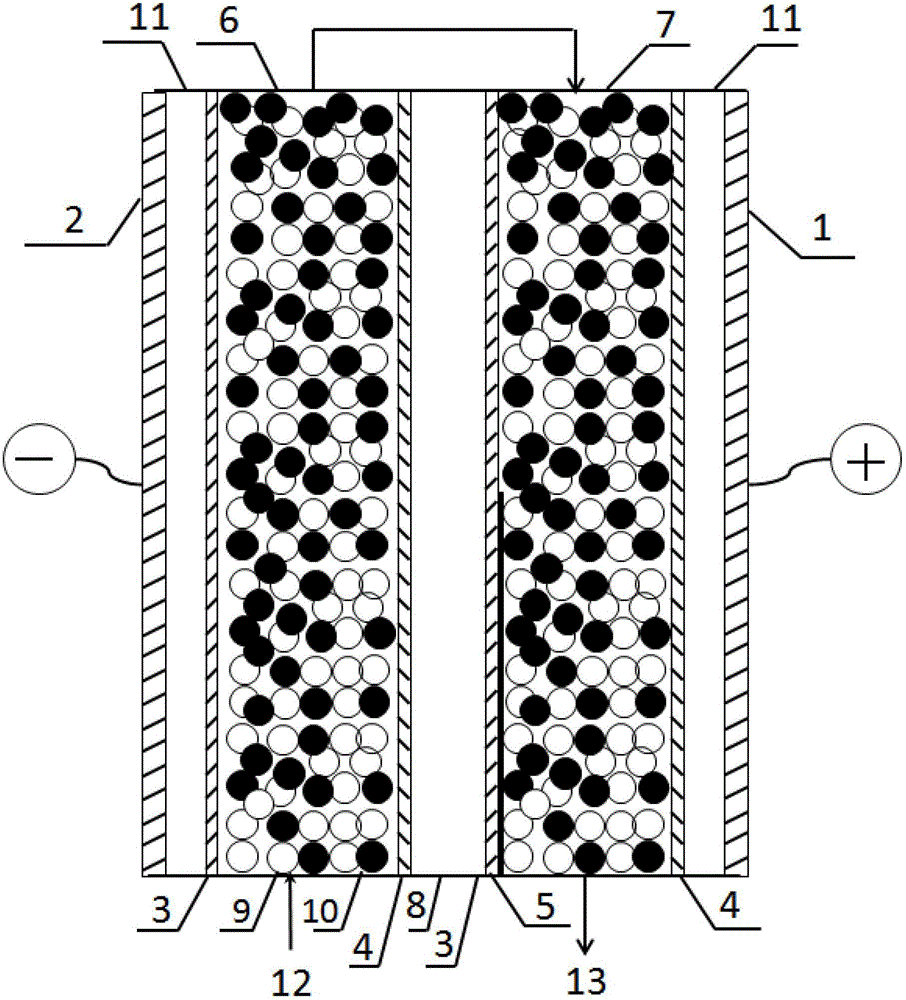
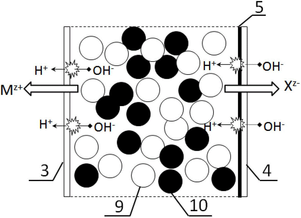
[0032] In this example, the EDI device is one level and two sections, such as figure 1 As shown, there are two light chambers, one concentrated chamber and two pole chambers between the electrodes. A ruthenium dioxide electrode is used as the anode, and a stainless steel electrode is used as the cathode. The size of the separator in the concentrated chamber and the electrode chamber is 100×400×2mm, the size of the separator in the dilute chamber is 100×400×5mm, and the effective area of ​​the membrane is 250cm 2 , using domestic homogeneous anion-cation exchange membrane. The catalyst attached to the cation exchange membrane within the range of the second thin chamber 7 close to 60% of the outlet is chromium hydroxide, and the cation exchange membrane within the range of the first thin chamber 6 remains as it is. Domestic styrene-based strongly acidic cation exchange resin and strongly basic anion exchange resin are used, and the particle size of the resin is 0.5mm. The fil...

Embodiment 2

[0035] The device of embodiment 2, circulation flow process and operating steps etc. are substantially the same as embodiment 1, and difference with embodiment 1 is: the catalyzer attached in the scope close to 60% of outlet on the cation exchange membrane of the second light chamber is nickel hydroxide. Domestic heterogeneous anion and cation exchange membranes are used. After 24 hours of operation, the concentration of copper ions in the effluent of the electrodeionization chamber is lower than 0.22mg / L. After 500 hours of operation of the electrodeionization device, the removal capacity is normal and there is no downward trend. After 500 hours, use an atomic force microscope to observe the catalyst layer on the membrane surface, and the uniformity of catalyst adhesion is consistent with the initial one. Nickel hydroxide catalyst is slightly less effective than chromium hydroxide.

Embodiment 3

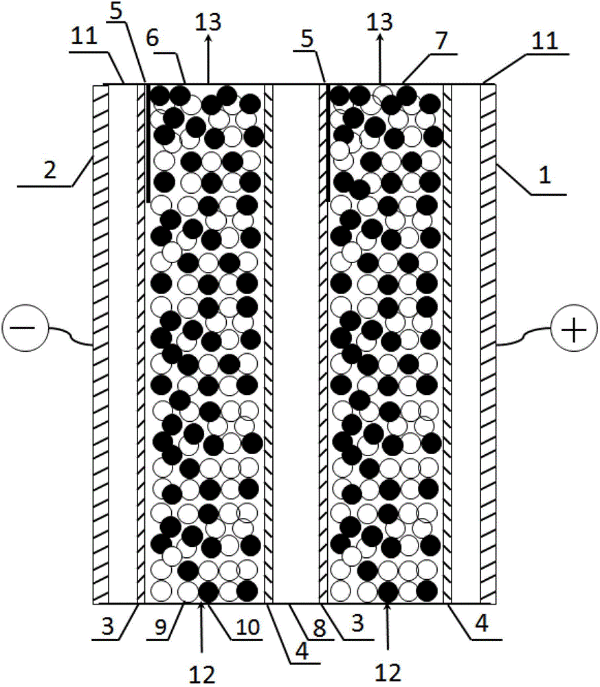
[0037] The device and operating steps of embodiment 3 are basically the same as embodiment 1, and the difference with embodiment 1 is: the EDI device is one stage one section, as figure 2 As shown, the raw water flow rate is 30L / h, and the catalyst attached to the cation exchange membrane within the length range of 35% of the first and second desalination chamber outlets is chromium hydroxide. The filling ratio of the anion and cation exchange resins in the first and second thin chambers was 30% in the area where the catalyst was attached, and 60% in the other areas. After 24 hours of operation, the concentration of copper ions in the effluent of the electrodeionization chamber is lower than 4.0mg / L. After 500 hours of long-term operation, the removal capacity of electrodeionization is normal, and there is no downward trend. After 500 hours of operation of the electrodeionization device, the atomic force microscope was used to observe the catalyst layer on the membrane surfa...


PUM

PropertyMeasurementUnit
Particle sizeaaaaaaaaaa

Abstract

The invention discloses an electrodeionization method and an electrodeionization apparatus for treating a low concentration ionic solution, and relates to the technology of desalination and ultrapure water treatment. Adhering a material capable of catalyzing water dissociation (5) to one side facing to a light chamber of a cation exchange membrane (3) of the electrodeionization apparatus. A conversion degree of a resin in the light chamber can be easily controlled by changing the adhering positions of the catalytic layer (5) of the cation exchange membrane (3), changing types of the catalytic materials and changing resin filling ratios of a bed layer of the light chamber, and then a removal degree of salt ions can be controlled. With the abovementioned way, relatively high resin regeneration degree can be realized in a relatively low applied voltage, so that a relatively high ion removal rate can be realized at a relatively low operating voltage. The electrodeionization apparatus can significantly reduce the applied voltage and energy consumption, thus reducing an operating cost, so the electrodeionization apparatus has important application value in the field of heavy metal ion removement and ultrapure water production.

Description

technical field [0001] The invention relates to an electrodeionization method and device for treating low-concentration ion solutions, which are used to improve the performance of the electrodeionization system, and more specifically relate to a water dissociation catalyst attached to the cation exchange membrane in the deionization chamber , to increase the degree of ion exchange resin regeneration in the desalination chamber bed, to reduce the voltage and energy consumption of the membrane stack, and to obtain a higher ion removal rate with lower energy consumption. Background technique [0002] In the field of ultrapure water preparation, electrodeionization (EDI) technology is gradually replacing the traditional ion exchange method and becoming the mainstream technology. EDI is a new composite separation process that fills the fresh water chamber of the electrodialyzer with ion exchange resin, combines ion exchange and electrodialysis, and realizes deep removal of low-co...

Claims


Application Information

Patent Timeline
IPC IPC(8): C02F1/469
CPCY02A20/124
Inventor 陆君陆鸿飞朱佳
Owner JIANGSU UNIV OF SCI & TECH
Learn More