
Oil-water separating device and method based on carbon nanotube film

A technology of oil-water separation device and carbon nanotube membrane, which is applied in the field of oil-water separation equipment and oil-water separation device based on carbon nanotube membrane, can solve the problems of narrow application range and high cost, and achieve stable properties, stable chemical properties, and high separation efficiency effect

Active Publication Date: 2012-10-31
SUZHOU INST OF NANO TECH & NANO BIONICS CHINESE ACEDEMY OF SCI
View PDF5 Cites 12 Cited by
  • Summary
  • Abstract
  • Description
  • Claims
  • Application Information

AI Technical Summary

Problems solved by technology

However, there are relatively few products for oil-water separation membranes, and they are mainly made of polymers or composite materials. Not only the cost is high, but also the material stability and reuse efficiency need to be further improved, and it is only suitable for specific oil-water mixing systems. Separation, narrow range of use

Method used


Image

  • Oil-water separating device and method based on carbon nanotube film
  • Oil-water separating device and method based on carbon nanotube film
  • Oil-water separating device and method based on carbon nanotube film

Examples


Embodiment 1

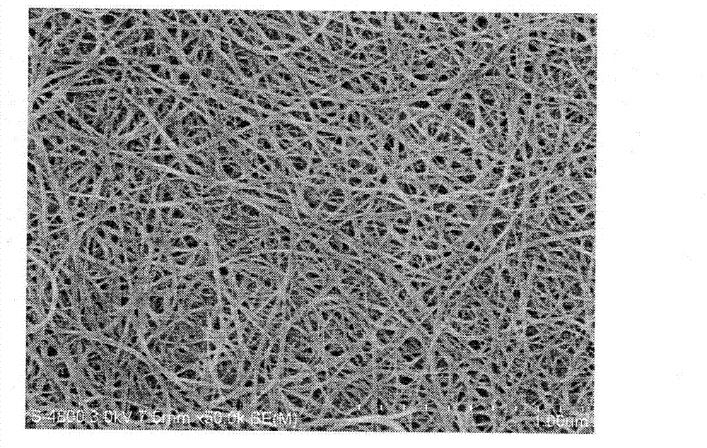
[0041] (1) Take an appropriate amount of carbon nanotubes dispersed in an aqueous solution, filter them into a membrane, and dissolve the substrate (such as a hydrophilic filter membrane) after drying. to obtain self-supporting carbon nanotube films (see figure 1 ). The carbon nanotube thin film obtained above is transferred to a ceramic membrane and placed in a separation container.

[0042] (2) Mix equal volumes of dichloromethane and water. After vigorous shaking, the stratification disappears, and then pour it into a separator. Under the action of pressure, the separation of dichloromethane and water is realized.

Embodiment 2

[0044] (1) Take an appropriate amount of carbon nanotubes dispersed in an aqueous solution, filter them into a membrane, and dissolve the substrate (such as a hydrophilic filter membrane) after drying. A self-supporting carbon nanotube film was obtained. The carbon nanotube thin film obtained above is transferred to a ceramic membrane and placed in a separation container.

[0045] (2) Mix dichloromethane and water with a volume ratio of 5:1. After vigorous shaking, the stratification disappears, and then pour it into a separator. Under the action of pressure, the separation of dichloromethane and water is realized.

Embodiment 3

[0047](1) Take an appropriate amount of carbon nanotubes dispersed in an aqueous solution, filter them into a membrane, and dissolve the substrate (such as a hydrophilic filter membrane) after drying. A self-supporting carbon nanotube film was obtained. The carbon nanotube thin film obtained above is transferred to a ceramic membrane and placed in a separation container.

[0048] (2) Mix dichloromethane and water with a volume ratio of 1:5. After vigorous shaking, the stratification disappears, and then pour it into a separator. Under the action of pressure, the separation of dichloromethane and water is realized.


PUM

PropertyMeasurementUnit
thicknessaaaaaaaaaa
pore sizeaaaaaaaaaa

Abstract

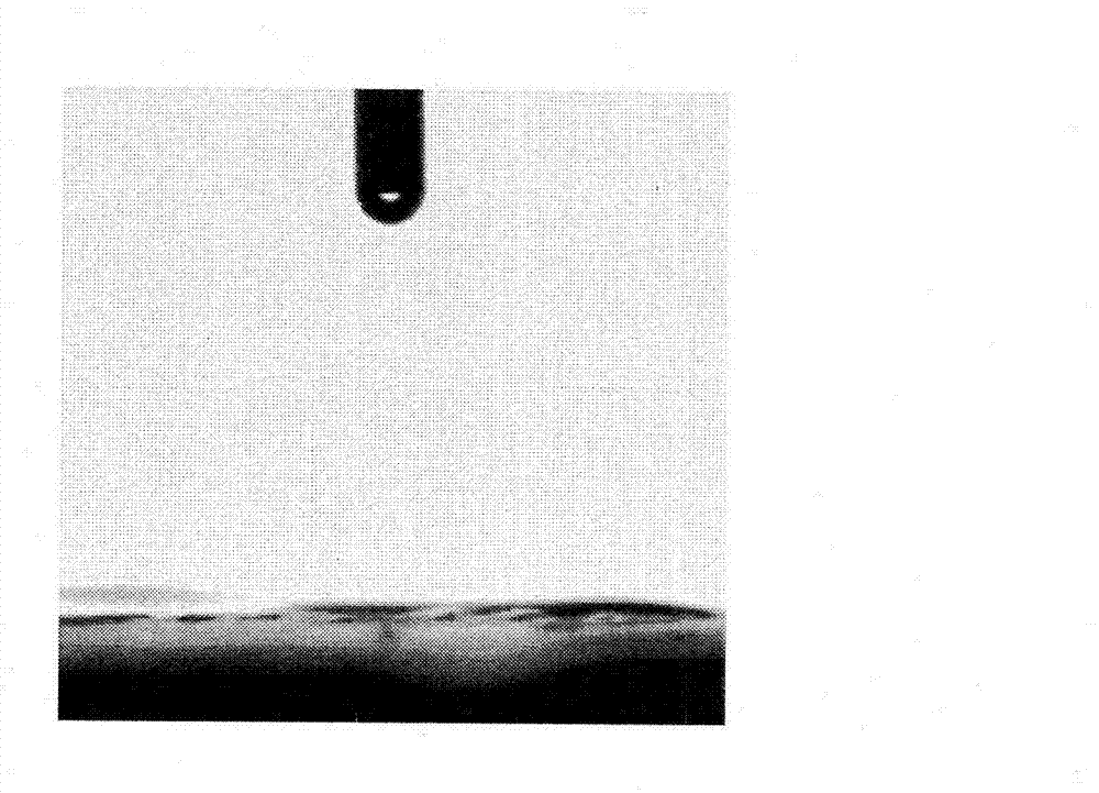
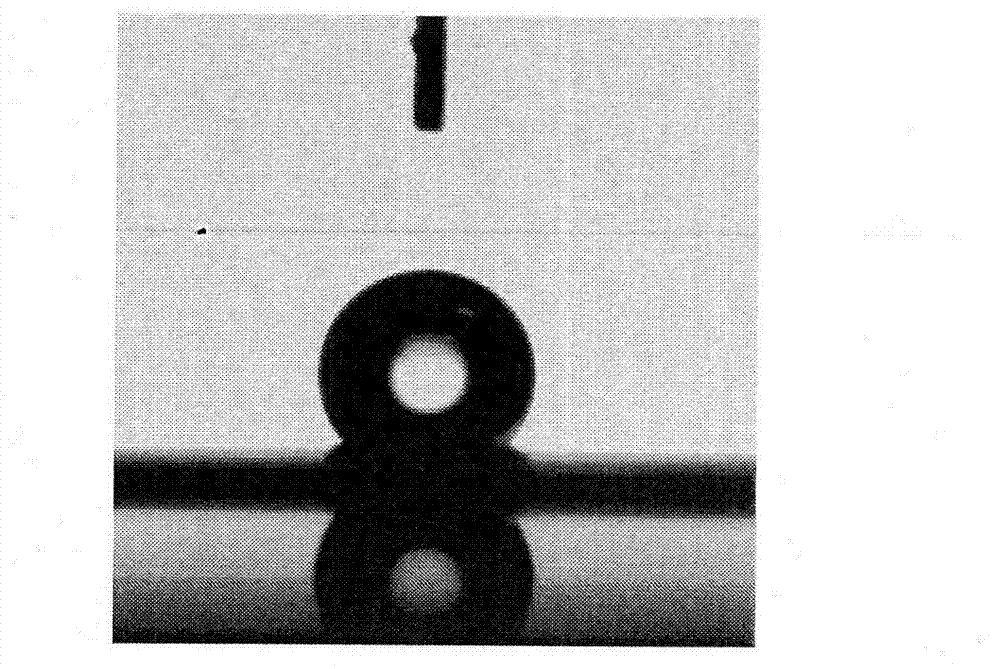
The invention discloses an oil-water separating device and method based on a carbon nanotube film. Separation of an oil-water mixed system is realized by taking a carbon nanotube film as a filter film. The carbon nanotube film is formed by a lattice of interwoven carbon nanotubes, the film thickness is 10-500 nanometers, the film pore diameter is 2-1,000 nanometers, the film surface has hydrophobic and oleophylic properties, the film has high acid resistance and alkali resistance, and the structure and performance of the film are stable when the pH value is 1-14. The oil-water mixed system comprises a system formed by directly mixing an oil phase with a water phase or emulsified oil water (water in oil type or oil in water type). The device and the method can be applied to low-cost, high-flux, efficient and rapid separation of various oil-water mixtures in the fields of production, life, petrochemical industry, machinery and the like.

Description

technical field [0001] The invention relates to an oil-water separation device and method, in particular to an oil-water separation device and method based on carbon nanotube membranes, belonging to the fields of functional materials, chemical engineering and environmental protection. Background technique [0002] Oil-water separation is a worldwide research hotspot. Due to the aggravation of industrial sewage problems in recent years and the occurrence of environmental problems such as offshore oil spills, oil-water separation materials have attracted more and more attention. Because oil-water separation is an interfacial problem, using materials with special wettability to prepare a porous membrane structure can separate oil-water mixtures according to their surface properties. However, there are relatively few products for oil-water separation membranes, and they are mainly made of polymers or composite materials. Not only the cost is high, but also the material stabilit...

Claims


Application Information

Patent Timeline
Patent Type & Authority Applications(China)
IPC IPC(8): B01D17/022
Inventor 靳健石准
Owner SUZHOU INST OF NANO TECH & NANO BIONICS CHINESE ACEDEMY OF SCI
Learn More