Light source alternate strobe synchronous camera shooting method and vision detection system

A synchronous camera, alternating stroboscopic technology, applied in the parts of the TV system, optical test defects/defects, TV and other directions, can solve the problems of limited accessibility, insufficient weld tracking, misjudgment, etc., to avoid information exchange. Interfere, facilitate image processing, and satisfy the effect of quality control

Inactive Publication Date: 2012-11-14
TSINGHUA UNIV
View PDF5 Cites 65 Cited by
  • Summary
  • Abstract
  • Description
  • Claims
  • Application Information

AI Technical Summary

Problems solved by technology

[0003] The existing methods for image capture of welds mainly include: 1. Use line structured light (mostly laser structured light) to irradiate the groove or weld surface, and obtain the edge position of the weld according to the distortion of the structured light strip in the captured image Information, the deficiency of this method: for the situation where the three-dimensional structure of the groove or weld is not obvious, such as the cover welding tracking of multi-layer multi-pass welding, the automatic guidance of non-destructive testing of post-weld grinding welds, etc., the structured light is not obvious distortion, it is difficult to obtain accurate edge position information, and the unevenness or impurities on the surface of the welding workpiece may also cause misjudgment of the edge, which cannot guarantee stable and reliable tracking
2. Using a black and white or color camera to capture the appearance of the weld surface and monitor the welding process cannot achieve shape measurement, defect determination based on image technology, and weld formation quality evaluation
3. Use dual cameras to capture the linear laser projected on the weld position and the weld pool respectively, and perform weld tracking and molten pool observation respectively, or use dual cameras to obtain multi-line structured light images and images under natural light or arc light illumination , the disadvantage of this method: the use of dual cameras increases the volume of the sensing system, which greatly limits the accessibility of the mechanism in actual production (especially robotic welding applications)
4. Push the filter to the front of the lens before the welding starts through the linkage mechanism, and remove it from the front of the lens after the welding is over. This method cannot achieve simultaneous acquisition of multiple characteristics of the object to be measured during the welding process
5. The molten pool and the solidified weld are collected in different areas of the image for processing. This method cannot achieve different optical features for the same object.
6. When shooting, the laser light source that irradiates the weld area and the line laser structure light source are lit at the same time, and the image that the line laser light strip and the surrounding weld seam exist at the same time is obtained. This method is insufficient: the weld seam is simultaneously illuminated by the high-brightness surface light source When illuminated by line structured light sources, the grayscale information of the weld seam and the distortion of the structured light strip interfere with each other, which brings inconvenience to the subsequent image processing
[0004] To sum up, none of the existing technologies can achieve synchronous and real-time acquisition of multiple optical features at the same position of the object to be measured during the welding process using only one camera
However, in actual production, the weld seam is more complicated, and the visual detection method using a single feature is often not enough to achieve stable and reliable weld seam tracking, let alone meet the needs of simultaneous tracking and quality control

Method used


Image

  • Light source alternate strobe synchronous camera shooting method and vision detection system
  • Light source alternate strobe synchronous camera shooting method and vision detection system
  • Light source alternate strobe synchronous camera shooting method and vision detection system

Examples


Embodiment 1

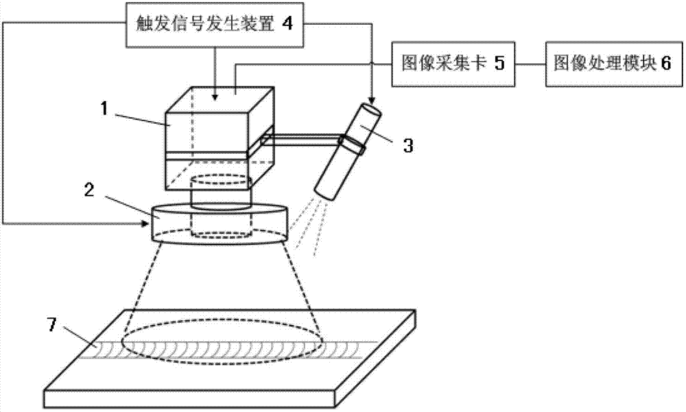
[0020] Such as figure 1 As shown, the visual inspection system of the present invention includes a camera 1 , an annular surface light source 2 , a multi-line laser structured light source 3 , a trigger signal generator 4 , an image acquisition card 5 and an image processing module 6 . A narrow-band filter (not shown in the figure) is set on the front end of the camera 1 lens. The surface light source 2 is fixed directly below the camera 1 through a peripheral bracket, and the multi-line laser structure light source 3 is fixed and set on the On the camera 1 side, the light plane of the multi-line laser structured light source 3 is at 45° to the optical axis of the camera 1 lens. The output end of the trigger signal generating device 4 is respectively connected with the trigger interface of the camera 1, the surface light source 2 and the multi-line laser structure light source 3 to control it to work, the output end of the camera 1 is connected to the input end of the image ac...

Embodiment 2

[0035] This embodiment takes the defect on the surface of the weld as the object to be tested as a specific embodiment to further illustrate the process of the light source alternate strobe and synchronous camera method. This embodiment has the same structure as the visual inspection system adopted in Embodiment 1. The visual inspection system is used for visual inspection after welding is completed.

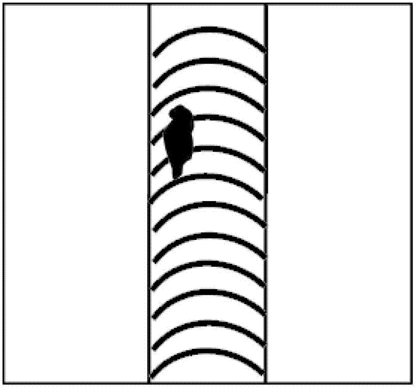
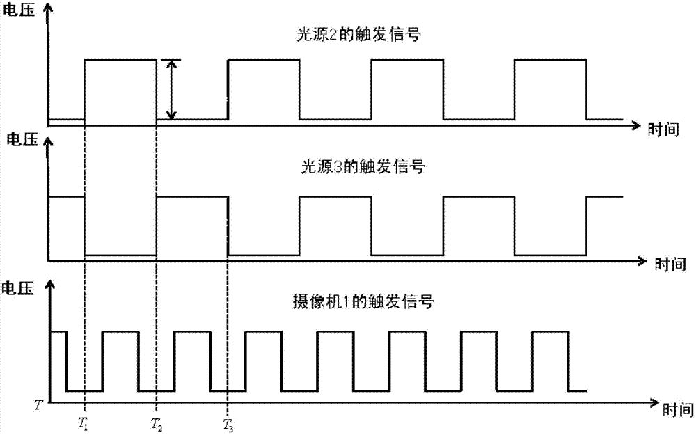
[0036] Such as figure 2 , as shown in Figure 3, during detection, the LED monochromatic surface light source 2 is irradiated vertically on the surface of the weld, and the laser structured light source 3 is obliquely projected on the surface of the weld, and the direction of the linear light strip formed on the surface of the weld is perpendicular to the direction of the weld , using the light source alternate strobe synchronous imaging method of the above-mentioned embodiment 1 to capture the image of the weld surface defect, the process is: (such as figure 2 As shown) the t...

Embodiment 3

[0040] The structure of the visual detection system of this embodiment and embodiment 1 and embodiment 2 is basically the same, the difference is: two light sources 2,3 are respectively fixed on the both sides of CCD digital camera 1 by peripheral brackets, each light source The included angle between the normal direction of the light-emitting surface and the axis of the CCD digital camera 1 is 20-40 degrees. Before taking pictures, the CCD digital camera 1 axis is directly facing the metal groove 8. When taking pictures, the axis of the CCD digital camera 1 is perpendicular to the surface of the area to be measured.

[0041] Such as Figure 4 As shown, the present embodiment takes the high-reflectivity metal groove 8 as the object to be measured as a specific embodiment to illustrate the process of the light source alternate stroboscopic synchronous imaging method again, and adopts the light source alternate stroboscopic synchronous imaging method of the above-mentioned embo...


PUM


Abstract

The invention relates to a light source alternate strobe synchronous camera shooting method and a vision detection system. The light source alternate strobe synchronous camera shooting method is characterized in that the vision detection system is arranged and comprises a camera, a spike filter, light sources, a trigger signal generating device, an image collecting card and an image processing module; the vision detection system is placed above an object to be detected; the trigger signal generating device simultaneously sends multi-way synchronous square signals to a camera shutter and each of the light sources to trigger the camera shutter and the light sources to work; during one trigger period of the synchronous square signals, the light sources are alternately lightened to irradiate the object to be detected, during the period that each of the light sources is lightened, the camera shoots an image of the light source irradiated object to be detected and sends the image to the image processing module through the image collecting card; and during different trigger periods of the synchronous square signals, the light sources are alternately lightened or extinguished in certain frequency periods, and the camera alternately shoots images of the object to be detected until all the images of the object to be detected are collected. The light source alternate strobe synchronous camera shooting method and the vision detection system can be widely applicable to processes that objects to be processed are subjected to image shooting during groove detection, rear-time welding seam tracking, welding seam molding quality detection and the like in robot automatic welding.

Description

technical field [0001] The present invention relates to an image capturing method and detection system, in particular to a light source alternate strobe synchronous camera method and a visual detection system suitable for robotic automatic welding, weld seam tracking detection, post-weld non-destructive detection tracking and object surface detection . Background technique [0002] Welding visual inspection technology plays an important role in the development of welding automation and intelligence. This technology is widely used in advanced manufacturing fields such as automatic welding seam tracking (including automatic teaching before welding and online tracking), real-time control of welding quality, and nondestructive testing after welding. . The object features usually detected by welding visual inspection technology include the three-dimensional shape of the groove, the texture of the weld, the color, the law of reflection, the light and shadow features, the shape of...

Claims


Application Information

Patent Timeline
Patent Type & Authority Applications(China)
IPC IPC(8): H04N5/232G03B15/05B23K37/00G01N21/88
Inventor 邹怡蓉都东张文增王力曾锦乐
Owner TSINGHUA UNIV
Why Eureka
Try Eureka