Laser radar system and compound distance-measuring and speed-measuring method adopting sine-wave amplitude modulation and phase pulse code modulation of same

A laser radar and phase encoding technology, which is applied in radio wave measurement systems, measurement devices, and re-radiation, etc., can solve the problems of mutual restriction between laser radar range resolution and ranging range.

Inactive Publication Date: 2012-11-28
HARBIN INST OF TECH
View PDF4 Cites 32 Cited by
  • Summary
  • Abstract
  • Description
  • Claims
  • Application Information

AI Technical Summary

Problems solved by technology

[0003] In order to solve the problem that the distance resolution of the laser radar and the ranging range (fuzzy detection distance) are mutually restricted in the existing laser radar system ranging meth

Method used


Image

  • Laser radar system and compound distance-measuring and speed-measuring method adopting sine-wave amplitude modulation and phase pulse code modulation of same
  • Laser radar system and compound distance-measuring and speed-measuring method adopting sine-wave amplitude modulation and phase pulse code modulation of same
  • Laser radar system and compound distance-measuring and speed-measuring method adopting sine-wave amplitude modulation and phase pulse code modulation of same

Examples


specific Embodiment approach 1

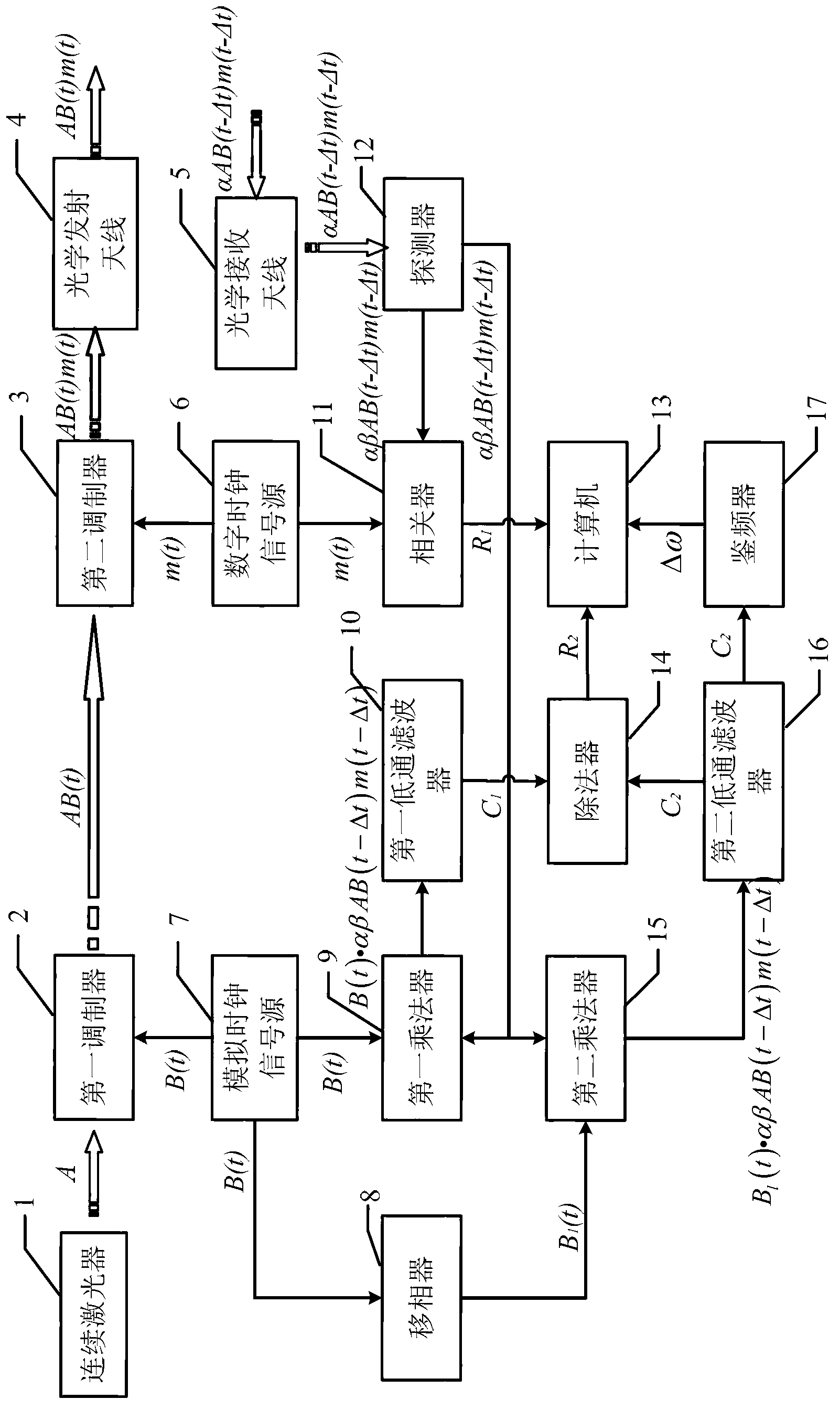
[0057] Specific implementation mode 1. Combination figure 1 Describe this embodiment in detail, the lidar system described in this embodiment, it comprises continuous laser device 1, first modulator 2, second modulator 3, optical transmitting antenna 4, optical receiving antenna 5, digital clock signal source 6, Analog clock signal source 7, phase shifter 8, first multiplier 9, first low-pass filter 10, correlator 11, detector 12, computer 13, divider 14, second multiplier 15, second low-pass filter 16 and discriminator 17,

[0058] The analog clock signal source 7 simultaneously transmits the continuous wave clock signal to the first modulator 2, the phase shifter 8 and the first multiplier 9,

[0059] The phase shifter 8 outputs the input continuous wave clock signal to the cosine continuous wave demodulation and mixing signal to the second multiplier 15,

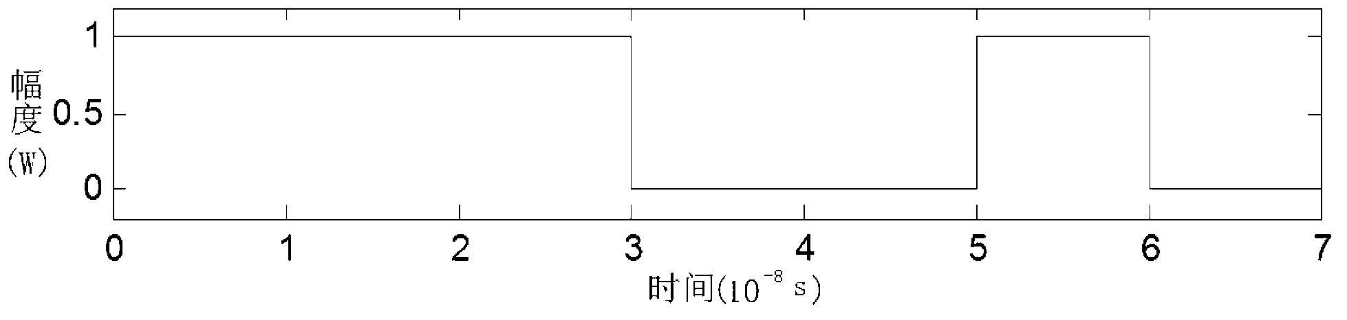
[0060] The digital clock signal source 6 sends the pulse phase encoding clock signal to the second modulator 3 and th...

specific Embodiment approach 2

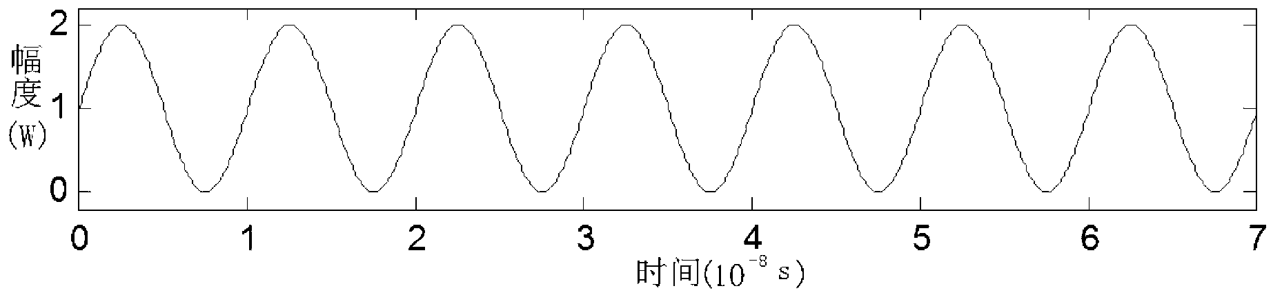
[0072] Embodiment 2. The difference between the complex ranging and velocity measuring methods based on the sinusoidal amplitude modulation-pulse phase code modulation of the laser radar system described in Embodiment 1 is that the analog clock signal source 7 simultaneously converts the continuous wave clock signal B(t) Transmitted to the first modulator 2, the phase shifter 8 and the first multiplier 9, the expression of the continuous wave clock signal B (t) is

[0073]

[0074] Among them, ω 0 Indicates the angular frequency of the AM continuous wave, t indicates the time, Indicates the initial phase of the AM continuous wave;

[0075] The phase shifter 8 shifts the phase of the input continuous wave clock signal B(t) Obtain the cosine continuous wave demodulated mixed frequency signal B 1 (t), output cosine continuous wave demodulated mixed frequency signal B 1 (t) to the second multiplier 15, the cosine continuous wave demodulation mixed frequency signal B 1 Th...

specific Embodiment approach 3

[0099] Specific Embodiment 3. The difference between this embodiment and the composite ranging and speed measuring method of the sinusoidal amplitude modulation-pulse phase code modulation of the laser radar system described in the specific embodiment 2 is that the angular frequency ω of the AM continuous wave 0 is of magnitude 10 7 ~10 8 .

[0100] The frequency of the amplitude-modulated continuous wave signal and the angular frequency ω of the phase-coded pulse signal in this specific embodiment 0 The amount is 10 7 ~10 8 , while the discriminator of the system only needs to discriminate the lower Doppler frequency shift signal Δω, the order of magnitude is about 10 0 ~10 2 , reduce the technical difficulty of the frequency discriminator, and make the radar have a higher velocity resolution.

[0101] The working process of this system is as follows: first, the analog clock signal from the analog clock signal source 7 is output to the first modulator 2, and the constan...


PUM


Abstract

The invention discloses a laser radar system and a compound distance-measuring and speed-measuring method adopting sine-wave amplitude modulation and phase pulse code modulation of the same, relating to the laser radar system and the compound distance-measuring and speed-measuring method adopting the sine-wave amplitude modulation and phase pulse code modulation of the same. The laser radar system and the compound distance-measuring and speed-measuring method adopting the sine-wave amplitude modulation-phase pulse code modulation of the same are invented in order to solve the problem of mutual limitation of range resolution and distance measurement range of the laser radar of the conventional laser radar system distance measurement method. The laser radar system performs sine-wave amplitude and pulse code compound modulation on the light intensity of the light beams to form a signal waveform. The modulation way of the signals is the amplitude modulation way; the sequence is that a signal with a constant amplitude value is firstly subjected to the sine-wave amplitude modulation and then subjected to the pulse amplitude modulation, so that moving speed and moving distance of the target can be output; and as the Doppler frequency shift caused by the target movement is obtained through the sine-wave amplitude demodulation, the moving speed of the target is thereby obtained. The laser radar system and the compound distance-measuring and speed-measuring method adopting the sine-wave amplitude modulation and phase pulse code modulation of the same, disclosed by the invention, are suitable for the field of radar.

Description

technical field [0001] The invention relates to the field of laser radar. Background technique [0002] There are three ranging methods for the lidar system, pulse ranging method, phase ranging method and pulse compression method (including pulse phase encoding and chirp technology). Each method has its advantages and limitations in terms of resolution, ranging range, and blur detection distance. The pulse ranging method has a longer ranging range, and its resolution is determined by the laser pulse width and the system time synchronization accuracy. In order to obtain high distance resolution, the pulse ranging method needs narrower pulse width and higher signal synchronization accuracy, which puts forward higher requirements for system design. The ranging range of the phase ranging method is equal to half of the wavelength of the modulation signal, and the distance resolution of the phase ranging method is inversely proportional to the ranging range of the system, so it ...

Claims


Application Information

Patent Timeline
IPC IPC(8): G01S17/32G01S7/483
Inventor 吴龙赵远张勇靳辰飞刘丽萍吴杰
Owner HARBIN INST OF TECH
Why Eureka
Try Eureka