
Piezoresistance/piezoelectric composite material, manufacturing method of material, sensor utilizing material and manufacturing method of sensor

A piezoelectric composite material and sensor technology, which is applied in the direction of using electric/magnetic devices to transmit sensing components, can solve the problems of dynamic vibration signal sensitivity, static signal insensitivity, and low sensing accuracy, and achieve good synchronous monitoring capabilities, The effect of high durability and high frequency response

Inactive Publication Date: 2013-02-13
QINGDAO TECHNOLOGICAL UNIVERSITY
View PDF6 Cites 57 Cited by
  • Summary
  • Abstract
  • Description
  • Claims
  • Application Information

AI Technical Summary

Problems solved by technology

For example, the technology of Chinese Patent No. ZL02132967.2, the electrical properties of cement matrix materials mixed with various conductive functional components (carbon black, nickel powder, carbon fiber, carbon nanotubes, etc.) will change with the change of external load / deformation The piezoresistive sensor formed by the piezoresistive effect is sensitive to (quasi) static signals, but not sensitive to dynamic vibration signals, and the sensing accuracy is low
For example, the Chinese patent No. ZL201010523624.3 technology, using the cement matrix material mixed with fine piezoelectric ceramic (PZT) powder or directly encapsulating the PZT sheet with resin concrete, the charge density at both ends of the block electrode will change with the external load / deformation The piezoelectric sensor formed by the changing (inverse) piezoelectric effect is mainly sensitive to dynamic vibration signals and insensitive to (quasi) static signals. It has low intrinsic structural toughness and is susceptible to shrinkage cracking of concrete pavement and subsidence of roadbed. Defects such as the influence of the natural environment
At the same time, it does not involve the use of the inverse piezoelectric effect of the corresponding piezoelectric sensor to effectively collect and store the vibration energy of the driving machine and various circuit energy supply systems.

Method used


Image

  • Piezoresistance/piezoelectric composite material, manufacturing method of material, sensor utilizing material and manufacturing method of sensor
  • Piezoresistance/piezoelectric composite material, manufacturing method of material, sensor utilizing material and manufacturing method of sensor
  • Piezoresistance/piezoelectric composite material, manufacturing method of material, sensor utilizing material and manufacturing method of sensor

Examples


Embodiment 1

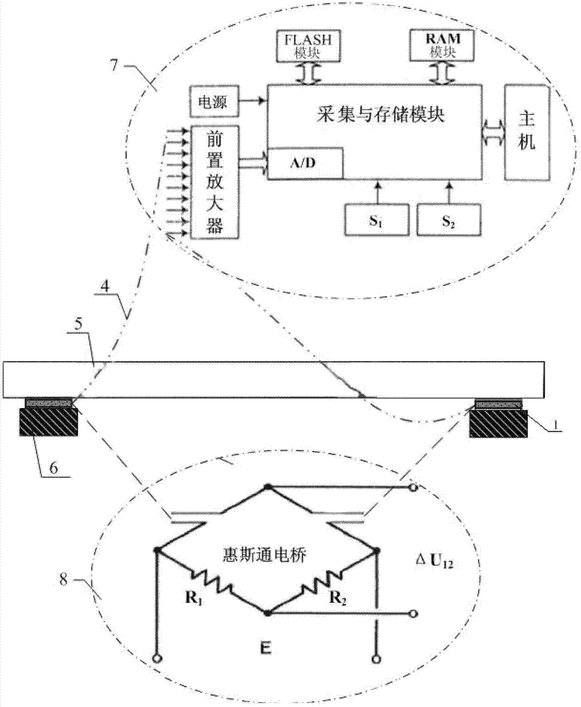
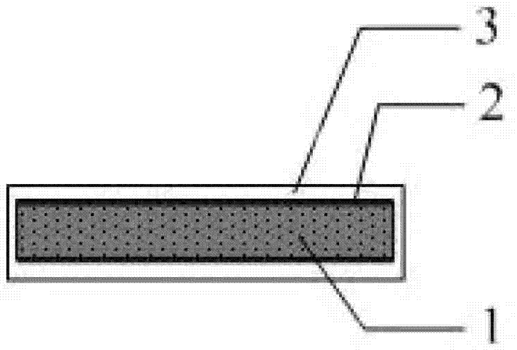
[0034] Such as figure 1 , figure 2As shown, the self-powered piezoresistive / piezoelectric composite sensor system between the bridge deck units 5 supported by the support 6 of the present invention includes an inductive element, a packaging shell, and a dynamic signal acquisition system 7, (quasi) static signal acquisition System 8. The inductive element includes a piezoresistive / piezoelectric composite material layer 1 and a pair of electrodes 2 located on the upper and lower surfaces of the piezoresistive / piezoelectric composite material. A pair of electrodes are connected through the electromagnetic shielding wire 4 that runs through the package shell. The electromagnetic shielding wire 4 is connected to the sensing signal acquisition and processing system through the shielding joint.

[0035] The preparation steps of the piezoresistive / piezoelectric composite material used are as follows:

[0036] (1) Preparation of micro / nano piezoelectric ceramic powder

[0037] Me...

Embodiment 2

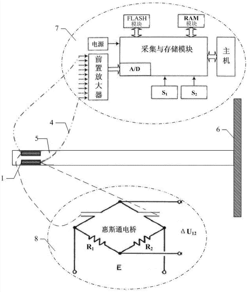
[0050] Such as image 3 As shown, the sensor system is embedded inside the cantilever deck unit 5 .

[0051] Others are with embodiment 1.

Embodiment 3

[0053] The preparation process and structure of the self-powered piezoresistive / piezoelectric composite sensor are the same as in Example 1. The difference is: the cement used is P.O.42.5R ordinary Portland cement, the micro / nano-scale piezoelectric ceramic powder is lead zirconate titanate powder with a particle size of 400-1100nm prepared by hydrothermal method, and the conductive filler is a diameter of 500nm graphene oxide is grafted with carbon nanofibers with a diameter of 60-100nm and a length of 6-30μm. The tough fiber is a polyimide fiber with a diameter of 5-20μm and a length of 8mm. The water-based resin and corresponding curing agent are water-based phenolic resin and supporting water-based Curing agent and superplasticizer are naphthalene sulfonate formaldehyde condensate series FDN, and the electrodes used are grid-type silver electrodes.

[0054] The obtained graphene oxide grafted carbon nanofiber / polyimide fiber / lead zirconate titanate / cement-based piezoresist...


PUM

PropertyMeasurementUnit
Particle sizeaaaaaaaaaa
Piezoelectric constantaaaaaaaaaa
Particle sizeaaaaaaaaaa

Abstract

The invention relates to a piezoresistance / piezoelectric material system and production and application methods of the piezoresistance / piezoelectric material system. The piezoresistance / piezoelectric composite material comprises the following components in parts by weight: 100 parts of cement, 105-500 parts of micro / nano grade piezoelectric ceramic powder body, 10-30 parts of fly ash, 15-50 parts of water, 0.01-2 parts of super plasticizer, 0.1-10 parts of toughness fiber and 0.01-15 parts of conductive fillers. A sensor utilizing the piezoresistance / piezoelectric composite material comprises a piezoresistance / piezoelectric composite material layer, wherein the upper surface and the lower surface of the piezoresistance / piezoelectric composite material layer are respectively provided with one electrode, the piezoresistance / piezoelectric composite material layer and the electrodes are coated in a package shell, the upper electrode and the lower electrode are connected by an electromagnetic shielding wire passing through the package shell, and the sensor is arranged between a bracket and a support bridge deck unit or is embedded in the support bridge deck unit. The sensor utilizing the material, disclosed by the invention, has intrinsic structure toughness and synchronous monitoring capability of covering a whole-frequency-domain static / dynamic traffic and structure parameters.

Description

technical field [0001] The invention relates to a self-powered piezoresistive / piezoelectric composite sensor system for a self-powered traffic and structural parameter synchronous monitoring sensor and a production and application method thereof. Background technique [0002] In recent years, with the rapid development of the national economy, the number of vehicles in my country has increased rapidly, and expressways, river (cross-sea) bridges, and urban viaducts / overpasses have been continuously built. Once a traffic accident or structural collapse occurs in these traffic structures, it will easily lead to congestion and casualties in the entire traffic system, and it will be difficult to repair in a short period of time, resulting in a significant drop in traffic capacity and immeasurable losses. Therefore, it is particularly necessary to carry out traffic control and structural health monitoring on the traffic structure of these hub areas and key road sections. At the s...

Claims


Application Information

Patent Timeline
IPC IPC(8): C04B28/06C04B28/04C04B35/491C04B35/626G01D5/12
Inventor 罗健林李秋义赵铁军高嵩
Owner QINGDAO TECHNOLOGICAL UNIVERSITY
Learn More