Double-electrode structure field emission luminous tube capable of regulating and controlling luminous patterns

A luminescent pattern and double-electrode technology, applied in discharge tubes, electrode devices and related components, cathode ray tubes/electron beam tubes, etc., can solve the problems of complex structure, high production cost, and inability to adjust and control, and achieve High luminous efficiency, low cost, and good pattern control effect

Inactive Publication Date: 2013-02-27
SHENYANG JIANZHU UNIVERSITY
View PDF3 Cites 0 Cited by
  • Summary
  • Abstract
  • Description
  • Claims
  • Application Information

AI Technical Summary

Problems solved by technology

[0004] It should be pointed out that the color and display graphics of field emission light-emitting diodes are mainly determined by the phosphor film, which cannot be adjusted and controlled after the coating is completed.
For example, the use of screen printing and other technologies to assemble matrix-addressable field emission cathodes can make the field emission phenomenon occur in a specific area, thereby realizing display pattern control, but its production cost is high, and the structure is quite fine and complex.

Method used


Image

  • Double-electrode structure field emission luminous tube capable of regulating and controlling luminous patterns
  • Double-electrode structure field emission luminous tube capable of regulating and controlling luminous patterns
  • Double-electrode structure field emission luminous tube capable of regulating and controlling luminous patterns

Examples


Embodiment 1

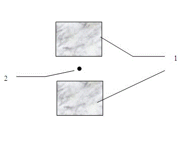
[0020] Illuminated control components and display graphics such as figure 2 shown.

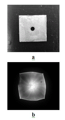
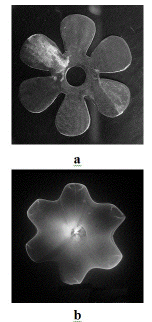
[0021] A carbon nanotube rope with a macroscopic length is used as a field emitter with an effective height of 2.5 mm and a diameter of 100 μm. The display pattern control component is made of two pieces of sodium-aluminosilicate glass 1, with a single piece size of 12x8 x 1 (mm), symmetrically arranged on both sides of the field emitter 2, with a distance of 6 mm; the flat anode is made of ITO conductive glass, coated with There is a phosphor film; the distance between the tip of the field emitter and the ITO anode is about 1 mm. In the working state, the applied voltage (positive potential) is applied to the ITO anode, and the field emitter is grounded. When the applied voltage is lower than 550V, the display pattern is in the shape of circular spots; when the applied voltage is higher than 570V, the display pattern is determined by the outer contour of the control component, which is clo...

Embodiment 2

[0023] The difference from Example 1 is that an external voltage (negative potential) is applied to the field emitter, and the ITO anode is grounded. The display pattern form is the same as in Example 1.

Embodiment 3

[0025] The body of the field emitter is a copper filament with an effective height of 5.0 mm and a diameter of 200 μm. There is a carbon nanotube film on the top surface. The display pattern control component is made of two ceramic plain sheets with a single piece size of 12 x 10 x 3 (mm), symmetrically arranged on both sides of the field emitter with a distance of 6 mm; the flat anode is made of ITO conductive glass, coated with Phosphor film; the distance between the field emitter tip and the ITO anode is about 0.5 mm. In the working state, the applied voltage (negative potential) is applied to the field emitter, and the ITO anode is grounded. When the applied voltage is higher than a certain potential difference, the display pattern changes from a circular spot to an approximate rectangle, similar to the outer contour of the control component.


PUM


Abstract

The invention relates to the technical field of lamination and display, in particular to a double-electrode structure field emission luminous tube capable of regulating and controlling luminous patterns and an assembling method of the double-electrode structure field emission luminous tube capable of regulating and controlling the luminous patterns. In the invention, a macroscopic field emitter with a large height-diameter ratio is assembled on a conducting substrate, on the surface, the local or the whole of the emitter, a carbonaceous nanotube, a nanowire, a nanofiber or a graphene sheet is used as a field emission source, pattern control assemblies are symmetrically arranged at the periphery of the field emitter, conductive glass coated with a fluorescent power film is used as an anode which is parallel to and opposite to a cathode conductive substrate, and a luminous structure is arranged in a vacuum sealed glass cavity, and is communicated with the outer part through leads. According to the invention, by utilizing the special emitting current-voltage relationship and the electron operation track change rule of the macroscopic field emission tip with the large height-diameter ratio under a special medium maintenance condition, the luminous display patterns of the double-electrode structure field emission luminous tube under the condition that the impressed voltage exists or a controller is in an insulation state can be controlled and changed.

Description

technical field [0001] The invention relates to the technical field of light emission and display, in particular to a double-electrode structure field emission light-emitting tube with an adjustable and controllable light-emitting pattern and an assembly method thereof. Background technique [0002] Light Emitting diode (Light Emitting diode) referred to as LED, its light-emitting principle is to use the radiation effect of the recombination of electrons and holes in the PN junction to emit visible light; the materials used are mostly semiconductor light-emitting substances, such as gallium (Ga) and arsenic (As) or phosphorus (P) compounds have different chemical compositions, and the luminous color (luminous wavelength) of the material is also different. The manufacturing process and structure of this type of LED are relatively complicated, the color variety is single, and the luminous brightness is low. [0003] Different from traditional LEDs, field emission luminescent...

Claims


Application Information

Patent Timeline
Patent Type & Authority Applications(China)
IPC IPC(8): H01J29/48H01J29/02H01J29/70
Inventor 佟钰刘俊秀夏枫张婷曾尤
Owner SHENYANG JIANZHU UNIVERSITY
Why Eureka
Try Eureka