Steel slag powder producing method employing roller press

A technology of steel slag powder and roller press, which is applied in grain processing, etc., can solve the problems of unreachable iron selection rate of ball mill, unclean iron removal, and difficult control of product fineness, so as to realize high value-added utilization and improve heat energy utilization efficiency and improve product quality

Inactive Publication Date: 2013-04-17
ANSHAN IRON & STEEL GROUP CORPORATION
View PDF6 Cites 11 Cited by
  • Summary
  • Abstract
  • Description
  • Claims
  • Application Information

AI Technical Summary

Problems solved by technology

The problem of the ball mill grinding process is that the power consumption is high, reaching 70-80kwh / t, and the consumption of the iron grinding body is very large. The wear of the grinding body causes the iron content of the steel slag powder to be high, and the quality is affected.
The iron selection rate of the ball mill cannot reach below 0.1%, which affects the quality of building material products and cannot meet the requirements of building material products
[0003] The ball mill combined with grinding process system also has the problem of high power consumption, reaching 50-60 kwh / t. At the same time, the iron removal effect of the system is poor. There is only one magnetic drum type iron remover, and the iron removal is not clean. In the grinding circuit Circular enrichment of metal impurities occurs, which in turn affects the operating efficiency of the grinding system and the quality of the fine powder
At the same time, the fineness of the product is difficult to control. The first stage of the mill acts as a coarse powder, and the second stage adopts an open-circuit ball mill system. The fineness of the product is low (the specific surface area is below 350㎡ / ㎏)

Method used


Image

  • Steel slag powder producing method employing roller press

Examples


Embodiment Construction

[0014] The specific embodiment of the present invention will be further described below in conjunction with accompanying drawing:

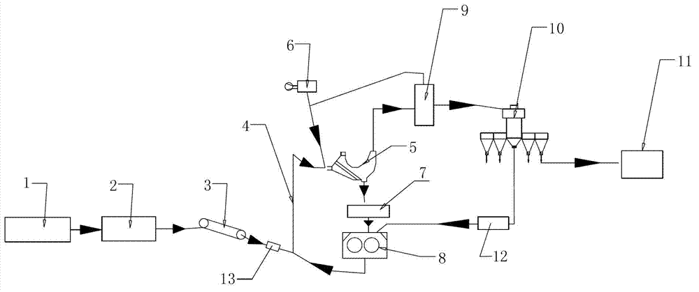
[0015] See figure 1 , is a process flow diagram of producing steel slag powder with a roller press of the present invention, comprising a steel slag tank 1, a feed bin 2, a belt conveyor 3, a chain bucket elevator 4, a static powder separator 5, and a hot blast stove 6 , high-efficiency magnetic separator 7, high-pressure roller press 8, cyclone separator 9, dynamic powder separator 10, finished product warehouse 11, magnetic separator 12, belt magnetic separator 13, high-pressure roller press 8, chain bucket Steel slag powder is produced in a closed-loop circuit composed of type hoist 4, static powder separator 5 and dynamic powder separator 10. The specific surface area of ​​the obtained steel slag powder product is above 450㎡ / ㎏, and the iron content is 0.1% after multi-channel magnetic separation equipment. Below, its technological process is ...


PUM

PropertyMeasurementUnit
specific surface areaaaaaaaaaaa
particle sizeaaaaaaaaaa

Abstract

The invention relates to the technical field of recycling of steel slag, in particular to a steel slag powder producing method employing a roller press. The method is characterized in that a closed loop formed by a high-pressure roller press, a bucket elevator, a static powder concentrator and a dynamic powder concentrator produces the steel slag powder; and the specific surface area of an obtained steel slag powder product is larger than 450m<2>/kg, the iron content is lower than 0.1% after the steel slag powder passes through a plurality of magnetic separation devices, and the negative pressure operation is adopted inside the static powder concentrator. Compared with the prior art, the method has the benefits that the closed loop and the negative pressure operation are adopted, therefore dust is little, the energy is saved, and the environment is protected; partial hot gas is recovered, and the heat energy utilization rate is improved; only the high-pressure roller press is adopted for grinding, so that the technological process is simple, and the investment is small; and the iron content is lower than 0.1%, the product quality is improved, the high value-added utilization of steel tailings is achieved, land-occupation stacking of the steel tailings is reduced, the environmental pollution is reduced, and the circular economy is developed.

Description

technical field [0001] The invention relates to the technical field of steel slag recycling, in particular to a method for producing steel slag powder with a roller press. Background technique [0002] Steel slag is a waste of metallurgical industry. A large amount of steel slag is produced in my country every year. The ferromagnetic substances in it are only magnetically separated during production. The steel tailing slag without magnetic separation accumulates in large quantities and occupies land, polluting the environment. The best way to utilize steel tailing slag is to apply it in the building materials industry, and grind it into steel slag powder for use in cement and concrete. At present, the grinding of steel slag powder mainly adopts ball mill process, ball mill combined grinding process or horizontal roller mill grinding process. The problem of the ball mill grinding process is that the power consumption is high, reaching 70-80kwh / t, and the consumption of the i...

Claims


Application Information

Patent Timeline
Patent Type & Authority Applications(China)
IPC IPC(8): B02C21/00
Inventor 苏兴文宋武李晓阳谷金生张志彪
Owner ANSHAN IRON & STEEL GROUP CORPORATION
Why Eureka
Try Eureka