Energy conservation and emission reduction method for fuel vehicle and energy conservation and emission reduction device special for fuel vehicle

A technology for energy saving, emission reduction, and vehicles. It is applied in the direction of engine lubrication, engine components, machines/engines, etc. It can solve the problems of reducing engine performance and life, increasing engine pollution, and reducing engine efficiency, so as to reduce vehicle emissions and save energy. Fuel consumption and emission reduction effects

Inactive Publication Date: 2013-05-08
HUNAN NENGCHUANG ENVIRONMENTAL PROTECTION TECH
View PDF8 Cites 0 Cited by
  • Summary
  • Abstract
  • Description
  • Claims
  • Application Information

AI Technical Summary

Problems solved by technology

Sludge and particulate matter that accumulates in the engine oil pan can also appear in the crankcase exhaust gases as environmental slag or dust and carbon from decomposed oil and fuel. Exhaust gases that escape into the crankcase contain water vapor and Sulfur dioxide, water vapor condenses in the engine oil to form foam, destroying the oil supply, sulfur dioxide meets water to form sulfurous acid, sulfurous acid meets oxygen in the air to form sulfuric acid, the appearance of these acidic substances not only deteriorates the engine oil, but also corrodes the parts , due to the combustible mixture and exhaust gas rushing into the crankcase, the pressure in the crankcase will increase, and the engine oil will seep from the crankshaft oil seal, crankcase gasket, etc. air pollution
[0003] The oil-containing vapor and crude gasoline entering the engine combustion chamber through the PCV system may delay ignition, thereby reducing engine efficiency; while particles and oil sludge dirt can further delay combustion and increase engine pollution, especially carbon monoxide and Hydrocarbon emissions, while particulate matter returning to the engine intake manifold can also damage cylinder walls and piston rings, reducing engine performance and life

Method used


Image

  • Energy conservation and emission reduction method for fuel vehicle and energy conservation and emission reduction device special for fuel vehicle
  • Energy conservation and emission reduction method for fuel vehicle and energy conservation and emission reduction device special for fuel vehicle
  • Energy conservation and emission reduction method for fuel vehicle and energy conservation and emission reduction device special for fuel vehicle

Examples


Embodiment 1

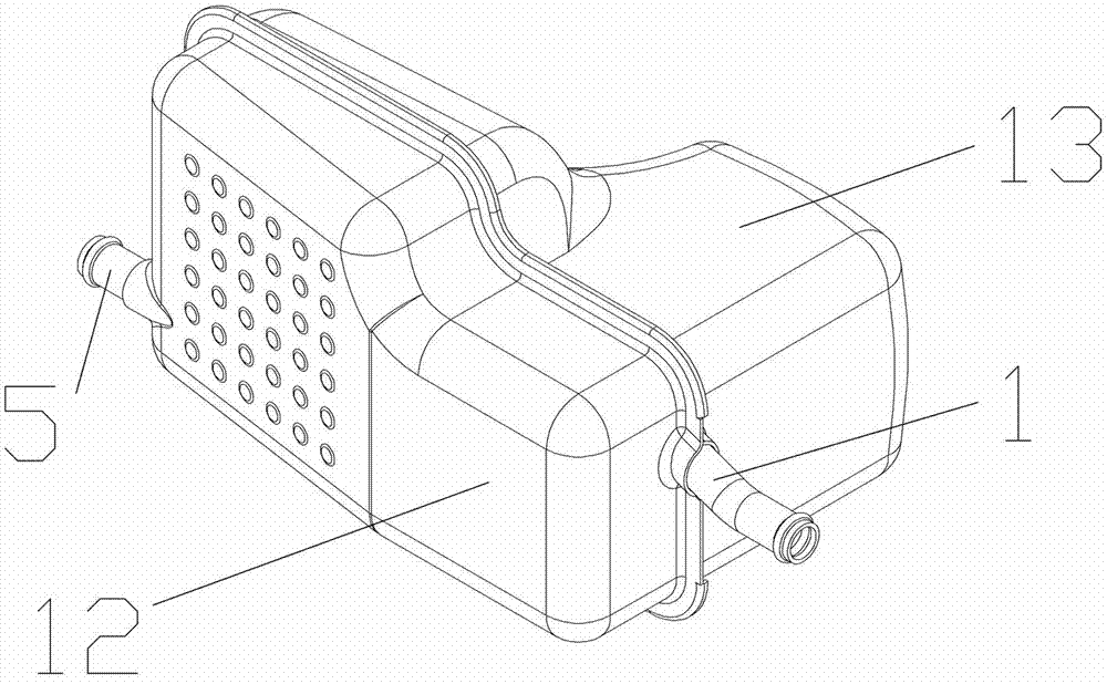
[0020] Embodiment 1, the present invention is mainly applied to various fuel vehicle engines, especially installed in the pipeline connecting the crankcase and the intake pipe, that is, between the engine and the intake throttle valve, the suction from the crankcase It can be installed on the front end of the engine cylinder head, and it is mainly made of a diffused swirl chamber and an oil-gas separator by using the oil-gas separation technology, and by using the principle of aerodynamics, the exhaust gas is in the energy-saving device Through compression and high-speed swirl, the decomposition force is improved, so that the oil vapor and combustible mixture in the exhaust gas are separated and then sent to the engine through the intake throttle. It can fully burn fuel to achieve fuel-saving effects, absorb harmful gases, and reduce emissions. Under normal circumstances, it can save more than 10-20% of fuel consumption and reduce vehicle emissions by 10%-40%. refer to Figur...

Embodiment 2

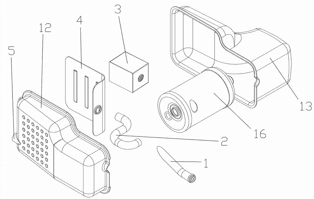
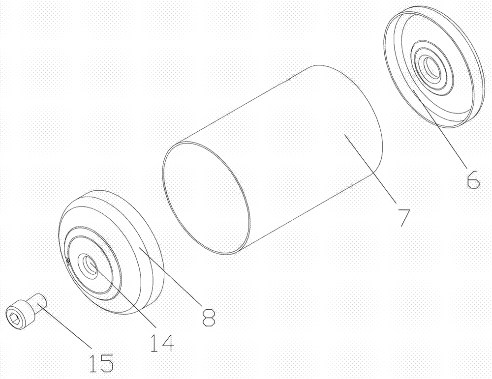
[0021] Embodiment 2, it also can be made of shell, heavy oil dirt separator 16 and light oil dirt filter 3 etc. in the present invention, and heavy oil dirt separator 16 and light oil dirt filter 3 are respectively installed in the both sides of housing cavity, and in heavy oil dirt filter An intermediate connecting pipe 2 is arranged between the separator 16 and the light oil filter 3; through holes matching the air inlet pipe 1 and the air outlet pipe 5 are respectively arranged at both ends of the casing, and a sewage through hole is arranged at the lower part of the casing; One end is sealed and fitted obliquely through the through hole of the shell and inserted into the heavy oil pollution separator 16, and is attached to the inner wall of the cylinder of the heavy oil pollution separator 16; Sewage pipe, the sewage pipe extends out of the shell through the sewage through hole provided at the lower part of the shell; an exhaust port is arranged on the upper part of the hea...

Embodiment 3

[0022] Embodiment 3, the height of the side where the heavy oil dirt separator 16 is installed on the shell of the present invention is greater than the height of the light oil dirt filter 3 , and the installation height of the light oil dirt filter 3 is higher than the bottom of the heavy oil dirt separator 16 . In order to facilitate the gas circulation flow more smoothly. refer to Figure 1 to Figure 5 , and the rest are the same as the above-mentioned embodiment.


PUM


Abstract

The invention discloses an energy conservation and emission reduction method for a fuel vehicle and an energy conservation and emission reduction device special for the fuel vehicle. The energy conservation and emission reduction method the for the fuel vehicle and the energy conservation and emission reduction device special for the fuel vehicle mainly solve the technical problems that fuel oil in an existing internal-combustion engine is not burned thoroughly, carbon is easily to deposit and the like. The technical scheme is that an exhaust gas separation device is installed in an engine crank case forced ventilation system, a diffusion rotational flow cavity and an oil-gas separation device are manufactured by mainly adopting of oil-gas separation technology, decomposition force can be improved when the exhaust gas is compressed and whirled with high speed in an energy-saving device by utilizing of an aerodynamics principle, and engine oil steam and combustible mixture in the exhaust gas are separated and delivered to the engine through an air inlet shutter. The fuel is enabled to combust fully, and therefore fuel saving effect is achieved, and discharge quantity is reduced. Under normal condition, fuel consumption can be saved by 10-20%, and at the same time, vehicle emissions of the vehicle can be reduced by 10-40%. The energy conservation and emission reduction device special for the fuel vehicle can be widely applied to engines of various fuel vehicles.

Description

technical field [0001] The invention relates to a method for reducing emissions of fuel vehicles, in particular to a technical proposal for separation by a device used for treating crankcase exhaust pollutants of fuel vehicles. Background technique [0002] At present, cars have been owned by more and more consumers, and have evolved from luxury goods to ordinary means of transportation. Vehicles with internal combustion engines use reciprocating pistons to drive a crankshaft to transmit torque. The recovery and use of mixed gas and exhaust gas is not only beneficial to improve the economy of the engine but also reduce the emission pollution of the engine; in addition to combustion gas, the ventilation gas of the crankcase also contains various amounts of unburned gasoline vapor, raw gasoline, engine oil And oil mist, which mainly includes gasoline fractions, lubricating oil fractions and hydrocarbon deposits. Sludge and particulate matter that accumulates in the engine oi...

Claims


Application Information

Patent Timeline
IPC IPC(8): F01M11/08
Inventor 周伟波
Owner HUNAN NENGCHUANG ENVIRONMENTAL PROTECTION TECH
Why Eureka
Try Eureka