Energy conservation and emission reduction method for fuel vehicle and energy conservation and emission reduction device special for fuel vehicle
A technology for energy saving, emission reduction, and vehicles. It is applied in the direction of engine lubrication, engine components, machines/engines, etc. It can solve problems such as reducing engine efficiency, reducing engine performance and life, and increasing engine pollution, so as to reduce emissions and reduce vehicle pollution. Emissions and fuel consumption saving effects
- Summary
- Abstract
- Description
- Claims
- Application Information
AI Technical Summary
Problems solved by technology
Method used
Image
Examples
Embodiment 1
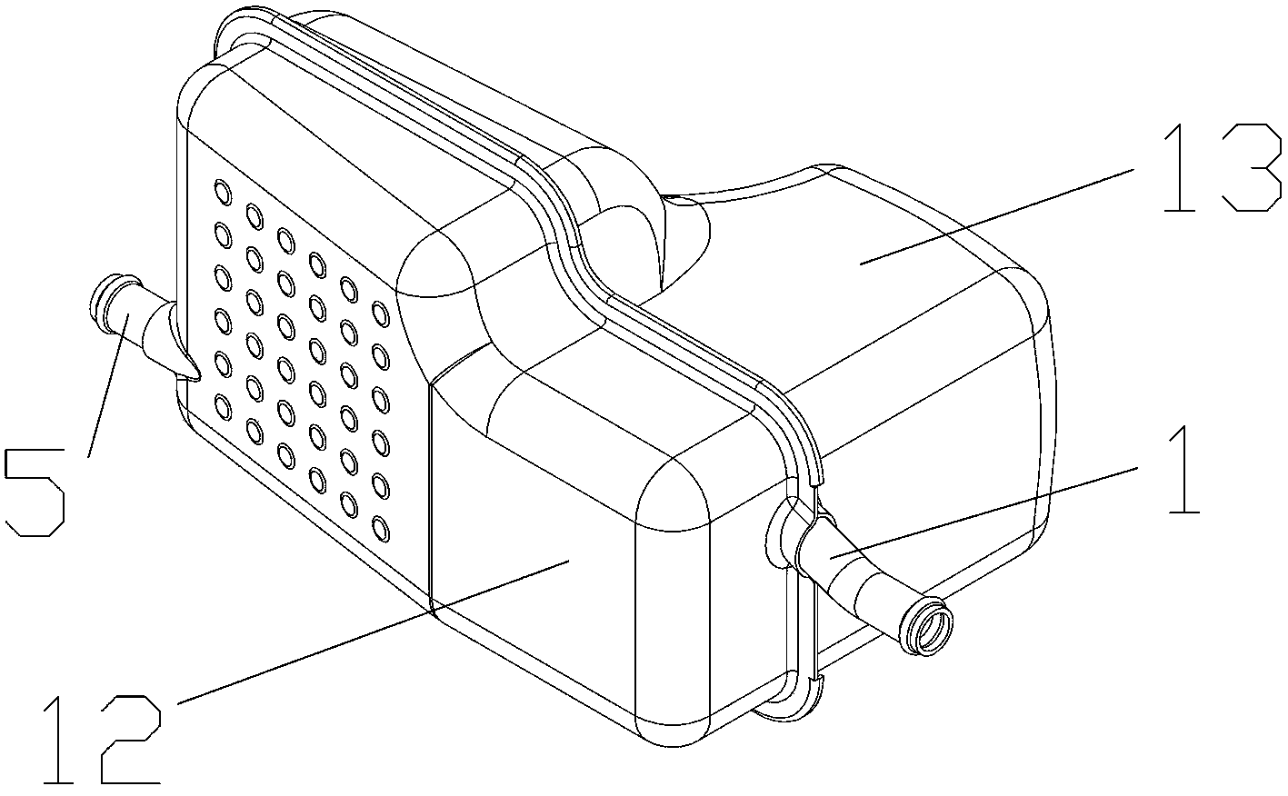
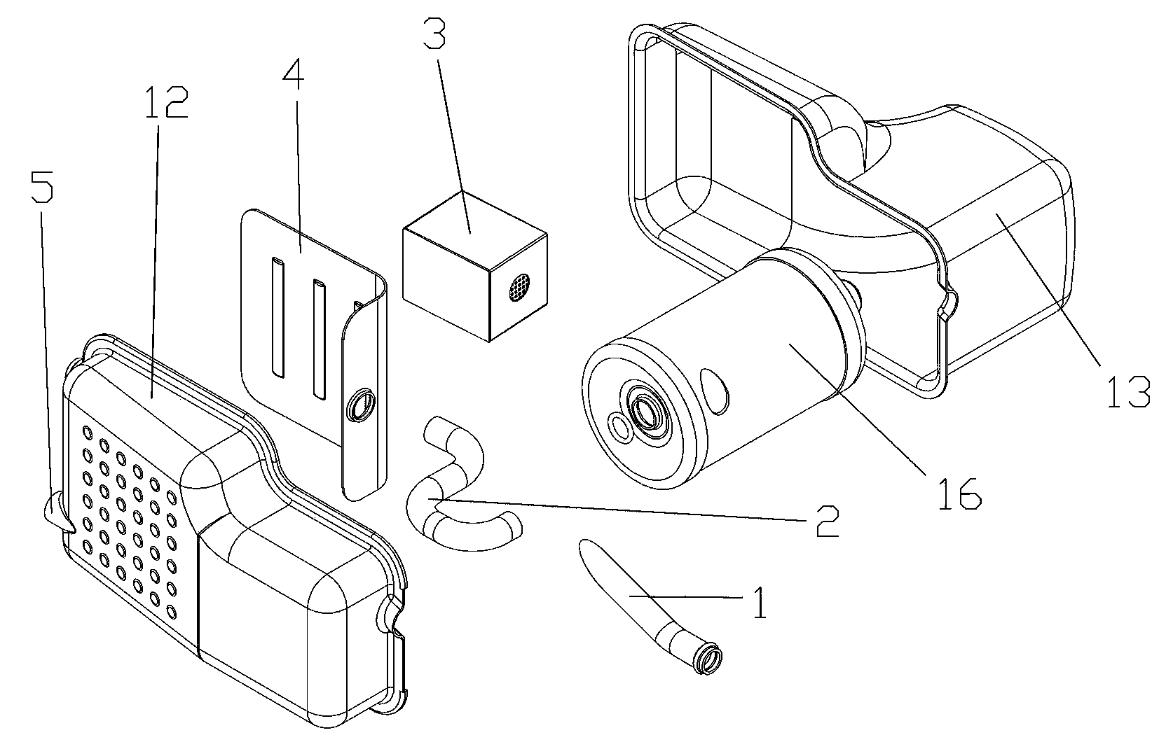
[0020] Embodiment 1, the present invention is mainly applied to various fuel vehicle engines, especially installed in the pipeline connecting the crankcase and the intake pipe, that is, between the engine and the intake throttle valve, the suction from the crankcase It can be installed on the front end of the engine cylinder head, and it is mainly made of a diffused swirl chamber and an oil-gas separator by using the oil-gas separation technology, and by using the principle of aerodynamics, the exhaust gas is in the energy-saving device Through compression and high-speed swirl, the decomposition force is improved, so that the oil vapor and combustible mixture in the exhaust gas are separated and then sent to the engine through the intake throttle. It can fully burn fuel to achieve fuel-saving effects, absorb harmful gases, and reduce emissions. Under normal circumstances, it can save more than 10-20% of fuel consumption and reduce vehicle emissions by 10%-40%. refer to Figur...
Embodiment 2
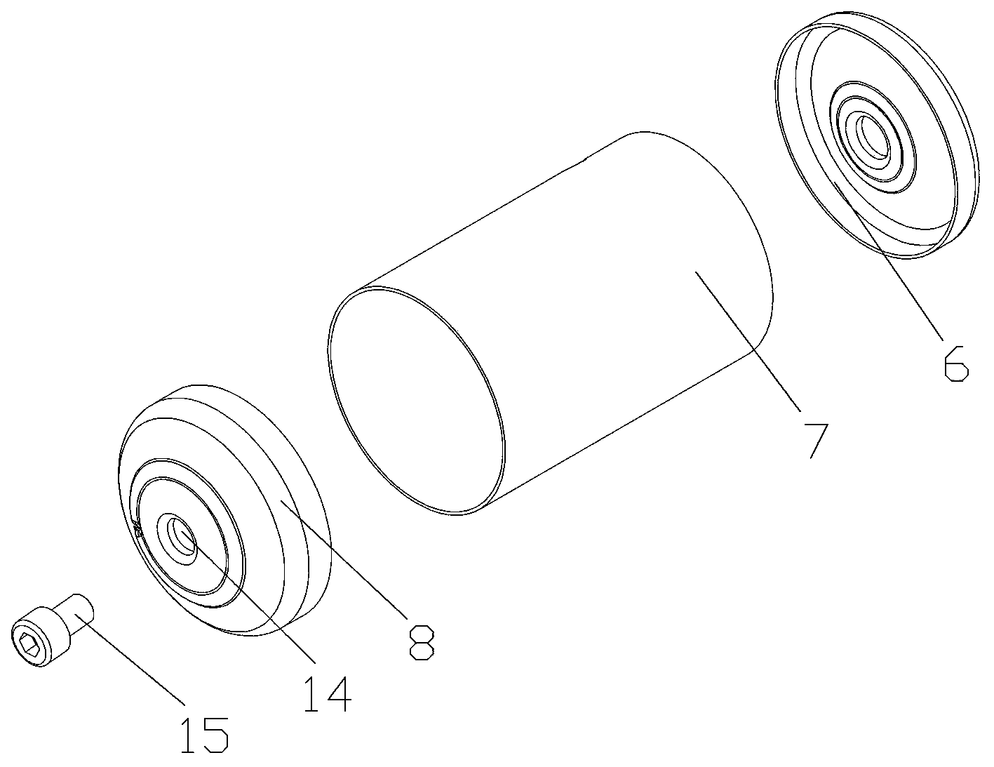
[0021] Embodiment 2, it also can be made of shell, heavy oil dirt separator 16 and light oil dirt filter 3 etc. in the present invention, and heavy oil dirt separator 16 and light oil dirt filter 3 are respectively installed in the both sides of housing cavity, and in heavy oil dirt filter An intermediate connecting pipe 2 is arranged between the separator 16 and the light oil filter 3; through holes matching the air inlet pipe 1 and the air outlet pipe 5 are respectively arranged at both ends of the casing, and a sewage through hole is arranged at the lower part of the casing; One end is sealed and fitted obliquely through the through hole of the shell and inserted into the heavy oil pollution separator 16, and is attached to the inner wall of the cylinder of the heavy oil pollution separator 16; Sewage pipe, the sewage pipe extends out of the shell through the sewage through hole provided at the lower part of the shell; an exhaust port is arranged on the upper part of the hea...
Embodiment 3
[0022] Embodiment 3, the height of the side where the heavy oil dirt separator 16 is installed on the shell of the present invention is greater than the height of the light oil dirt filter 3 , and the installation height of the light oil dirt filter 3 is higher than the bottom of the heavy oil dirt separator 16 . In order to facilitate the gas circulation flow more smoothly. refer to Figure 1 to Figure 5 , and the rest are the same as the above-mentioned embodiment.
PUM
 Abstract
Description
Claims
Application Information
 - R&D
- Intellectual Property
- Life Sciences
- Materials
- Tech Scout
- Unparalleled Data Quality
- Higher Quality Content
- 60% Fewer Hallucinations
Browse by: Latest US Patents, China's latest patents, Technical Efficacy Thesaurus, Application Domain, Technology Topic, Popular Technical Reports.
© 2025 PatSnap. All rights reserved.Legal|Privacy policy|Modern Slavery Act Transparency Statement|Sitemap|About US| Contact US: help@patsnap.com


