Method for improving stability of infrared gas detection system based on digital potentiometer

A gas detection system, digital potentiometer technology, applied in instruments, measuring devices, scientific instruments, etc., can solve the problems of confusion of light intensity changes, affecting the measurement accuracy and long-term stability of infrared spectrum absorption technology, measurement errors, etc., to eliminate The influence of the instability of the light source, the improvement of the system stability, the effect of a wide range of applications

Inactive Publication Date: 2013-06-12
SHANDONG UNIV
View PDF4 Cites 11 Cited by
  • Summary
  • Abstract
  • Description
  • Claims
  • Application Information

AI Technical Summary

Problems solved by technology

However, because optical devices such as lasers, couplers, collimators, and optical fibers are susceptible to changes in temperature and stress environmental factors, the light generation power and optical coupling efficiency will be changed, so that the intensity of the transmitted light after passing through the gas chamber will change. The light intensity changes caused by absorption loss are confused and cause measurement errors
Affects the measurement accuracy and long-term stability of infrared spectroscopy absorption technology

Method used


Image

  • Method for improving stability of infrared gas detection system based on digital potentiometer
  • Method for improving stability of infrared gas detection system based on digital potentiometer
  • Method for improving stability of infrared gas detection system based on digital potentiometer

Examples


Embodiment 1

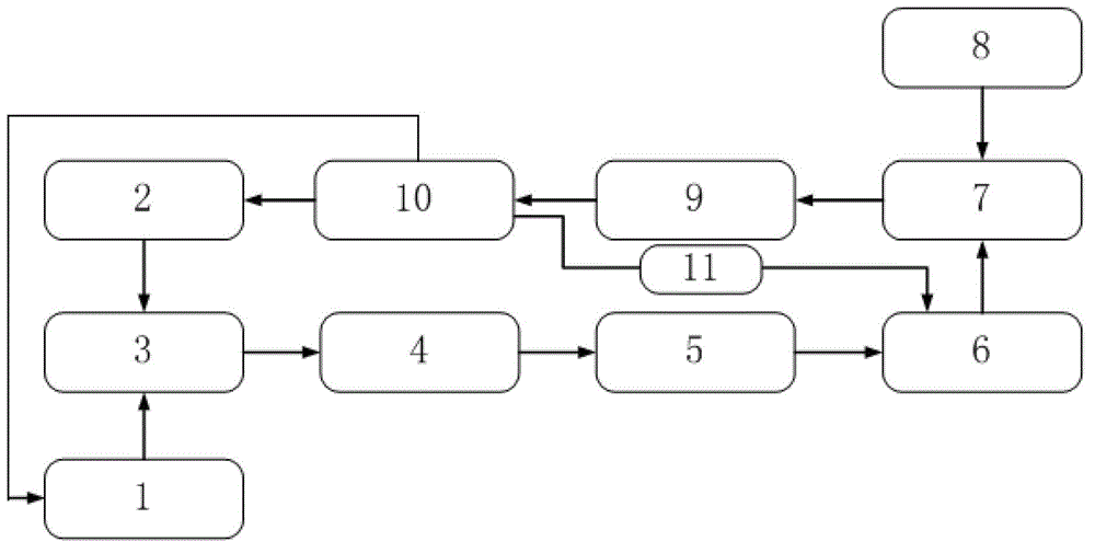
[0041] Embodiment 1 of the present invention such as figure 2 Shown: an infrared gas detection system, including a current drive circuit 1, a temperature control circuit 2, a DFB laser 3, a gas chamber 4, a photodetector 5, an amplifier circuit 6, a differential circuit 7, a reference circuit 8, a filter circuit 9, Microprocessor 10, digital potentiometer 11, it is characterized in that DFB laser 3 is positioned at before gas chamber 4, and the input end of gas chamber 4 other end is connected with photodetector 5, and the output end of photodetector 5 is connected with amplifying circuit 6, amplifies The output end of the circuit 6 and the output end of the reference circuit 8 are respectively connected to the input end of the differential circuit 7, the output end of the differential circuit 7 is connected to the input end of the filter circuit 9, the output end of the filter circuit 9 is connected to the microprocessor 10, and the temperature control The circuit 2 is conne...

Embodiment 2

[0053] The process of using the above detection system to detect water vapor in the air chamber is as follows:

[0054] 1) Connect the detection system well; connect the power supply of each circuit module and single-chip microcomputer, debug the optical path and circuit to make it work normally; the gas to be tested is rushed into the gas chamber;

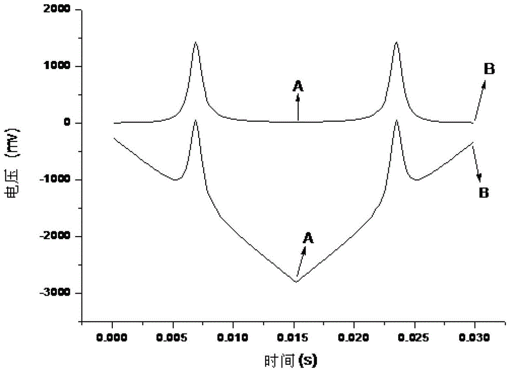
[0055] 2) Set the bridge resistance in the temperature control circuit to a fixed value and then keep it constant to realize the constant temperature control of the DFB laser: use the microprocessor to generate a current change of 48mA within 0.03S, and the change process increases from low to high from 24mA to 72mA, and then reciprocate from 72mA to 24mA from high to low. The set current range is realized in the form of a triangle wave corresponding to the output voltage in the microprocessor; because the change of the DFB laser drive current will cause DFB The change of the output wavelength of the laser, the voltage change outp...


PUM

PropertyMeasurementUnit
wavelengthaaaaaaaaaa

Abstract

The invention discloses a method for improving the stability of an infrared gas detection system based on a digital potentiometer, belonging to the field of gas detection. The method is implemented by a temperature control circuit, a current drive circuit, a DFB (Distributed Feed Back) laser device, a gas chamber, a photoelectric detector, a reference circuit, an amplification circuit, the digital potentiometer, a differential circuit, a filter circuit and a microprocessor. The method is characterized in that the digital potentiometer is taken as a gain resistor of the amplification circuit; and after the variation of a final wave form, acquired by the microprocessor, is processed, the magnification times of a transmission optical path electric signal is changed through feedback regulation on the resistance of the digital potentiometer, so that the aim of automatically compensating the fluctuation, caused by environment factors (except for gas absorption), of the optical power of transmission light, which passes through the gas chamber, is realized, and system measurement errors caused by the fluctuation are overcome. The system is simple in structure and easy to realize, has the characteristics of being high in long-term stability and insensitive to system environment change, and can be widely used in the field of free optical path and optical fiber gas detection.

Description

technical field [0001] The invention relates to a method for improving the stability of an infrared gas detection system based on a digital potentiometer. Specifically, the digital potentiometer feedbacks and adjusts the magnification of the electrical signal of the transmission optical circuit to automatically compensate for the transmission light caused by environmental factors (except gas absorption). The method of optical power fluctuation. Background technique [0002] The detection of micro-moisture content plays an important role in the power industry. Since the mid-1980s, with the rapid development of the power industry, sulfur hexafluoride (SF 6 ) electrical equipment are widely used, specifically including SF 6 Circuit Breaker, GIS Enclosed Combined Appliance, SF 6 Insulated transformers, voltage transformers, current transformers and various high-voltage bushings, etc. And at present, most of the projects under construction with a voltage level of 110kv and ab...

Claims


Application Information

Patent Timeline
Patent Type & Authority Applications(China)
IPC IPC(8): G01N21/35G01N21/3504
Inventor 常军朱存光王朋朋王强刘永宁魏巍高婷王福鹏
Owner SHANDONG UNIV
Why Eureka
Try Eureka