Method for removing conductive layer from ti-made fuel battery separation plate

A fuel cell and conductive layer technology, which is applied to fuel cell parts, cleaning methods using liquids, chemical instruments and methods, etc., can solve problems such as declining yield and recycling efficiency, and achieve high effect of loss

Inactive Publication Date: 2013-06-19
KOBE STEEL LTD
View PDF5 Cites 0 Cited by
  • Summary
  • Abstract
  • Description
  • Claims
  • Application Information

AI Technical Summary

Problems solved by technology

In addition, in the method in which a large loss of titanium material occurs when the conductive layer is removed, there is a problem of a decrease in yield (decrease in recycling efficiency)

Method used


Image

  • Method for removing conductive layer from ti-made fuel battery separation plate
  • Method for removing conductive layer from ti-made fuel battery separation plate
  • Method for removing conductive layer from ti-made fuel battery separation plate

Examples


Embodiment 1

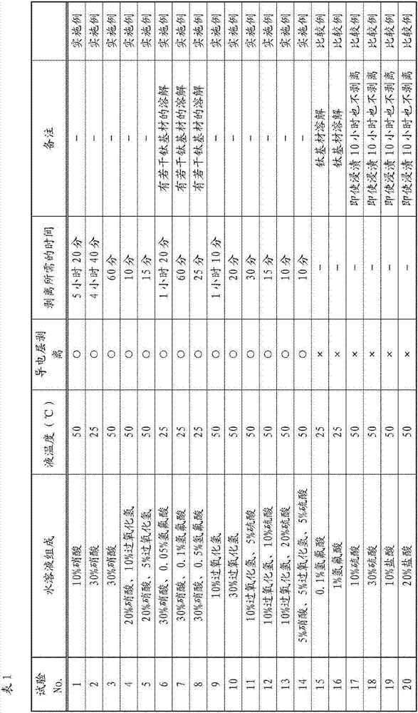
[0097] Next, with regard to the method for removing the conductive layer of the titanium fuel cell separator material of the present invention, Examples (Test Nos. 1 to 14) satisfying the requirements of the present invention and Comparative Examples (Test No. 15) not satisfying the requirements of the present invention are compared. ~20) to specify.

[0098] (Test material)

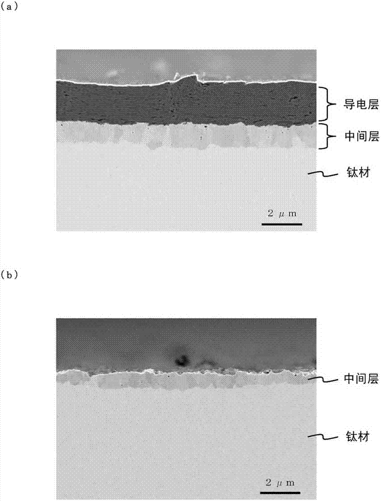
[0099] The substrate is made of pure titanium according to JIS Class 1. After coating the slurry containing expanded graphite powder on both sides of the substrate, the two-stage roller punching machine is used for crimping, and then in a vacuum environment (6.7×10 -3 Pa) at 700°C for 60 minutes, and then heat-treated under furnace cooling conditions. The above-mentioned treatment was used to manufacture a test material in which a carbon-based conductive material was covered (on both sides) on a base material formed of pure titanium as a conductive layer, and a titanium carbide-containing material was f...

Embodiment 2

[0115] By the same process as in Example 1, a carbon-based conductive material covering (both sides) a base material made of pure titanium as a conductive layer was produced, and a middle layer containing titanium carbide was formed between the conductive layer and the base material. The material of the layer is cut and processed into a size of 20×30mm.

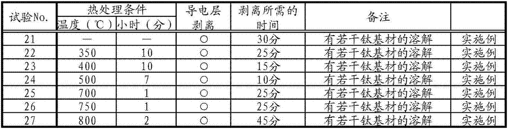
[0116] Then, a part was removed, and a heat treatment was performed at 350 to 750° C. for a predetermined time in an air atmosphere to prepare a test material.

[0117] (conductive layer removal test)

[0118] In the conductive layer removal test, 10 mass % nitric acid and 0.2 mass % hydrofluoric acid aqueous solution were used, 30 ml of the aqueous solution was put into a covered PP container (50 ml capacity), and the liquid temperature was adjusted to room temperature 50° C. for the test. In addition, the adjustment of the liquid temperature was performed using a constant temperature bath in the same manner as in Example 1...


PUM

PropertyMeasurementUnit
thicknessaaaaaaaaaa
thicknessaaaaaaaaaa
thicknessaaaaaaaaaa

Abstract

The invention provides a method for removing a conductive layer containing a carbon conductive material from a Ti-made fuel battery separation plate while inhibit loss of a substrate that is Ti material. The Ti-made fuel battery separation plate of the invention comprises: a conductive layer which contains the carbon conductive material and is formed on the substrate made of pure titanium or titanium alloys, and an intermediate layer which contains titanium carbide and is formed between substrate and the conductive layer; and the method is used for removing the conductive layer from the Ti-made fuel battery separation plate. The method is characterized by dipping the Ti-made fuel battery separation plate in a water solution containing any one of nitric acid and hydrogen peroxide, or in a water solution containing both of nitric acid and hydrogen peroxide.

Description

technical field [0001] The present invention relates to a method for removing a conductive layer from a titanium fuel cell separator material coated with a conductive layer containing a carbon-based conductive material on a base material formed of pure titanium or titanium alloy . Background technique [0002] As an energy source, a fuel cell that continuously extracts electricity by continuously supplying fuel such as hydrogen and an oxidant such as oxygen is expected. Unlike primary batteries such as dry batteries or secondary batteries such as lead storage batteries, they have high power generation efficiency and are hardly affected by the size of the system. In addition, since there is little noise and vibration, it can cover a variety of uses and scales. Specifically, fuel cells have developed solid polymer fuel cells (PEFC), alkaline electrolyte fuel cells (AFC), phosphoric acid fuel cells (PAFC), molten carbonate fuel cells (MCFC), solid oxide fuel cells type fuel c...

Claims


Application Information

Patent Timeline
Patent Type & Authority Applications(China)
IPC IPC(8): H01M8/02B08B3/08
CPCY02E60/50
Inventor 铃木顺佐藤俊树
Owner KOBE STEEL LTD
Why Eureka
Try Eureka