

Method for preparing gel diaphragm cell by in-situ polymerization and prepared battery
A diaphragm battery and in-situ polymerization technology, applied in secondary batteries, battery pack components, circuits, etc., can solve the problems of poor lyophilicity of the diaphragm, poor electrode contact, and high crystallinity of polymer molecules, so as to avoid the danger of liquid leakage situation, reduce energy attenuation, and reduce performance differences
- Summary
- Abstract
- Description
- Claims
- Application Information
AI Technical Summary
Problems solved by technology
Method used
Image


Examples
Embodiment 1
[0025] The lithium hexafluorophosphate electrolyte was dissolved in a mixed organic solvent of ethylene carbonate (EC) and diethyl carbonate (DEC) at a mass ratio of 1:1, and the electrolyte solution with a concentration of 1mol / L was prepared by conventional techniques. Add 10% vinyl chloride monomer and 1% azobisisobutyronitrile (AIBN) initiator to the electrolyte. From the moment when the electrolyte is prepared, the basic physical properties of the electrolyte are tested at room temperature every 10 days, and treated at 45°C for 6 hours and then 75°C for 4 hours, and a high-temperature gel experiment is performed to determine whether the initiator and the monomer are Inactivate. During storage, ensure that the electrolyte is well-sealed and protected from light, and record the temperature and humidity of the environment in detail to obtain the storage stability of the electrolyte under specific conditions. The measured data and phenomena in Table 1 show that the electroly...
Embodiment 2
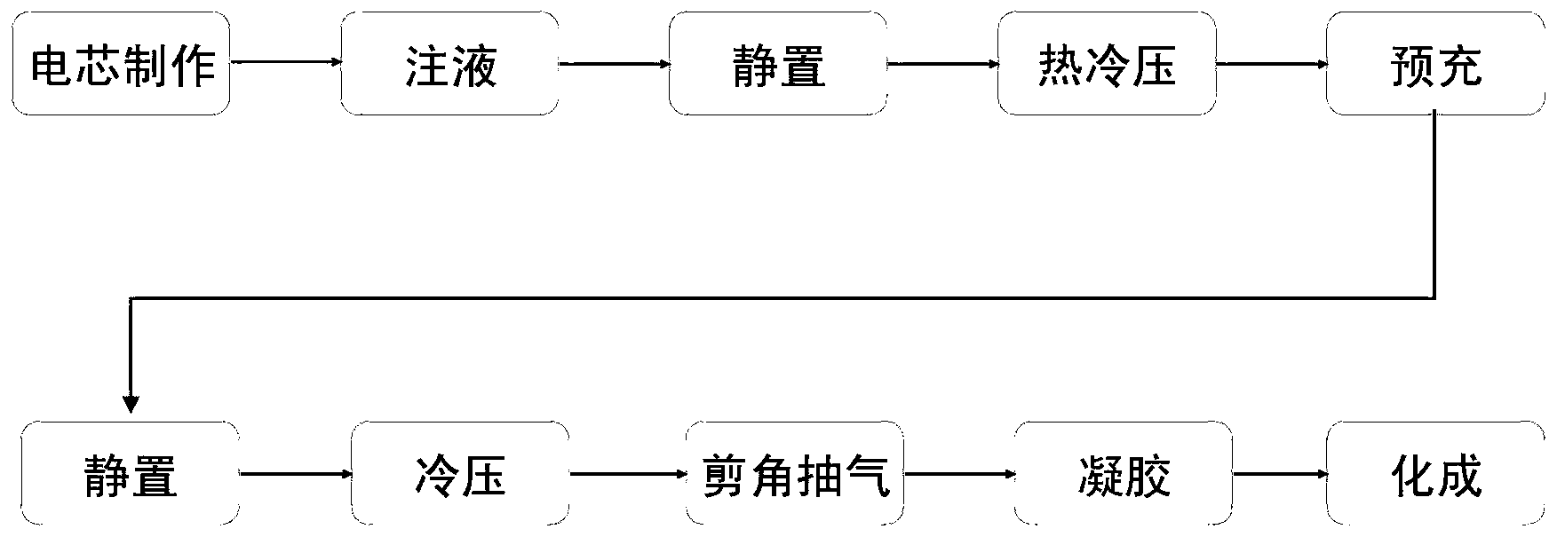
[0029] The polymer lithium electrolyte described in Example 1, the commercial lithium cobaltate positive electrode, the graphite negative electrode, and the polyethylene diaphragm are assembled into a liquid electrolyte battery, and the electrolyte and the diaphragm are gelled by using in-situ polymerization technology, Design gel battery, the specific in-situ polymerization process is as follows figure 1 shown. A winding battery is used, the capacity of the pole piece is about 2.4Ah, 11g of electrolyte is injected, and it is left to stand in vacuum at room temperature for 15 minutes. After sealing, the battery was left to stand at room temperature for 56 hours, hot-pressed at 30°C and pressure of 0.4MPa for 2 minutes, and then cold-pressed at 20°C for 2 minutes at the same pressure. The battery is precharged once with a constant current of 0.03C rate, and the precharge time is 200min. After the first pre-charge is completed, let it stand at room temperature for 35 hours, an...
Embodiment 3
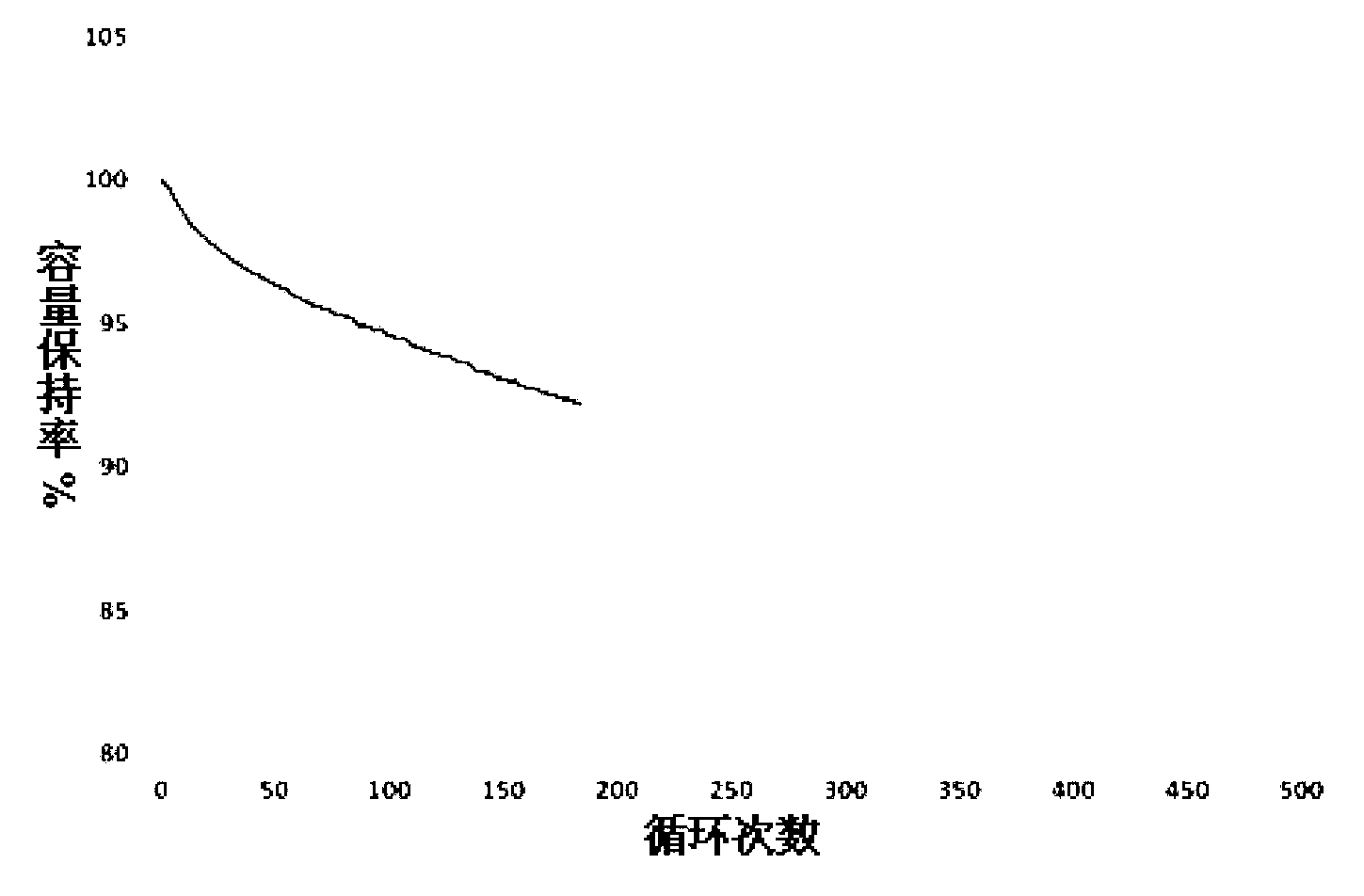
[0031]The design process of the gel separator battery produced by the in-situ polymerization process technology is as described in Example 2. The produced gel battery is charged to 4.2V with a constant current of 0.5C in the voltage range of 3.0 to 4.2V at 55°C, continued to be charged to 0.02C at a constant voltage of 4.2V, and then discharged to 3.0V at a constant current of 0.5C for cycle Performance tests, the results of which are as follows image 3 As shown, after 200 charge-discharge cycles, the capacity retention rate is above 95%, indicating the good cycle stability of the gel battery. At 25°C, the voltage range is between 3.0 and 4.2V, charge to 4.2V with a constant current of 0.5C, continue to charge with a constant voltage at 4.2V to 0.02C, and discharge at a constant current of 0.1C, 0.5C, and 1C respectively to obtain the discharge rate Performance graphs such as Figure 4 shown. The capacity retention rate is greater than 96% when discharged at 1C rate, indic...
PUM
 Abstract
Description
Claims
Application Information