Winding power inductor and production method thereof

A technology for manufacturing power inductors and components, applied in the manufacture of coils, electrical components, inductors/transformers/magnets, etc., can solve the problems of low space utilization, low saturation magnetic flux density, etc., achieve low DC impedance, and simple production process Effect

Active Publication Date: 2013-09-11
贵阳顺络迅达电子有限公司
View PDF9 Cites 18 Cited by
  • Summary
  • Abstract
  • Description
  • Claims
  • Application Information

AI Technical Summary

Problems solved by technology

[0002] The existing I-shaped winding glue-coated power inductor with a high degree of automation has a main frame made of nickel-zinc ferrite with a low saturation magnetic flux density, and the enameled wire is a round enameled wire with a low space utilization rate, which is difficult to While maintaining the corresponding inductance value in a smaller volume, it can withstand a larger current

Method used


Image

  • Winding power inductor and production method thereof
  • Winding power inductor and production method thereof
  • Winding power inductor and production method thereof

Examples


specific Embodiment approach 1

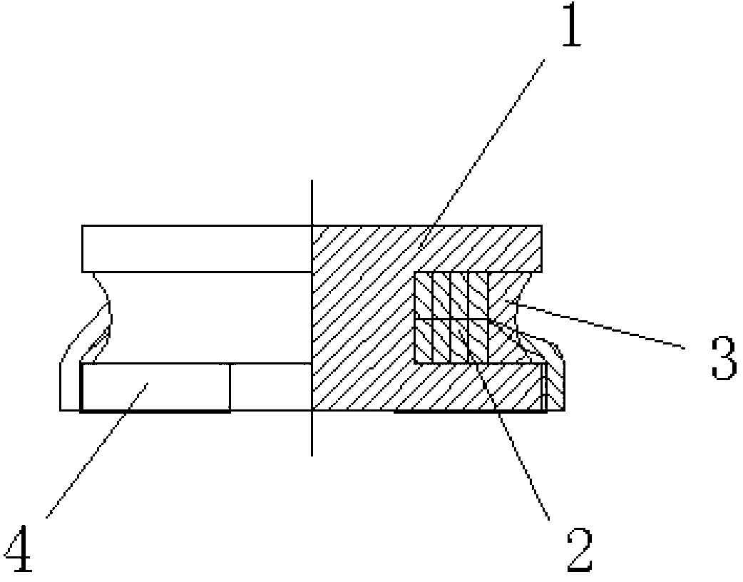
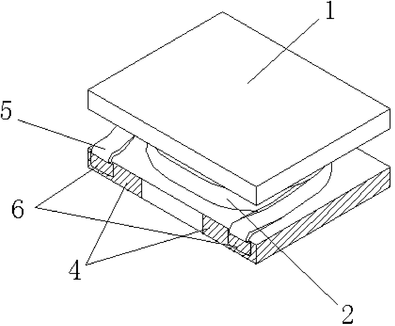
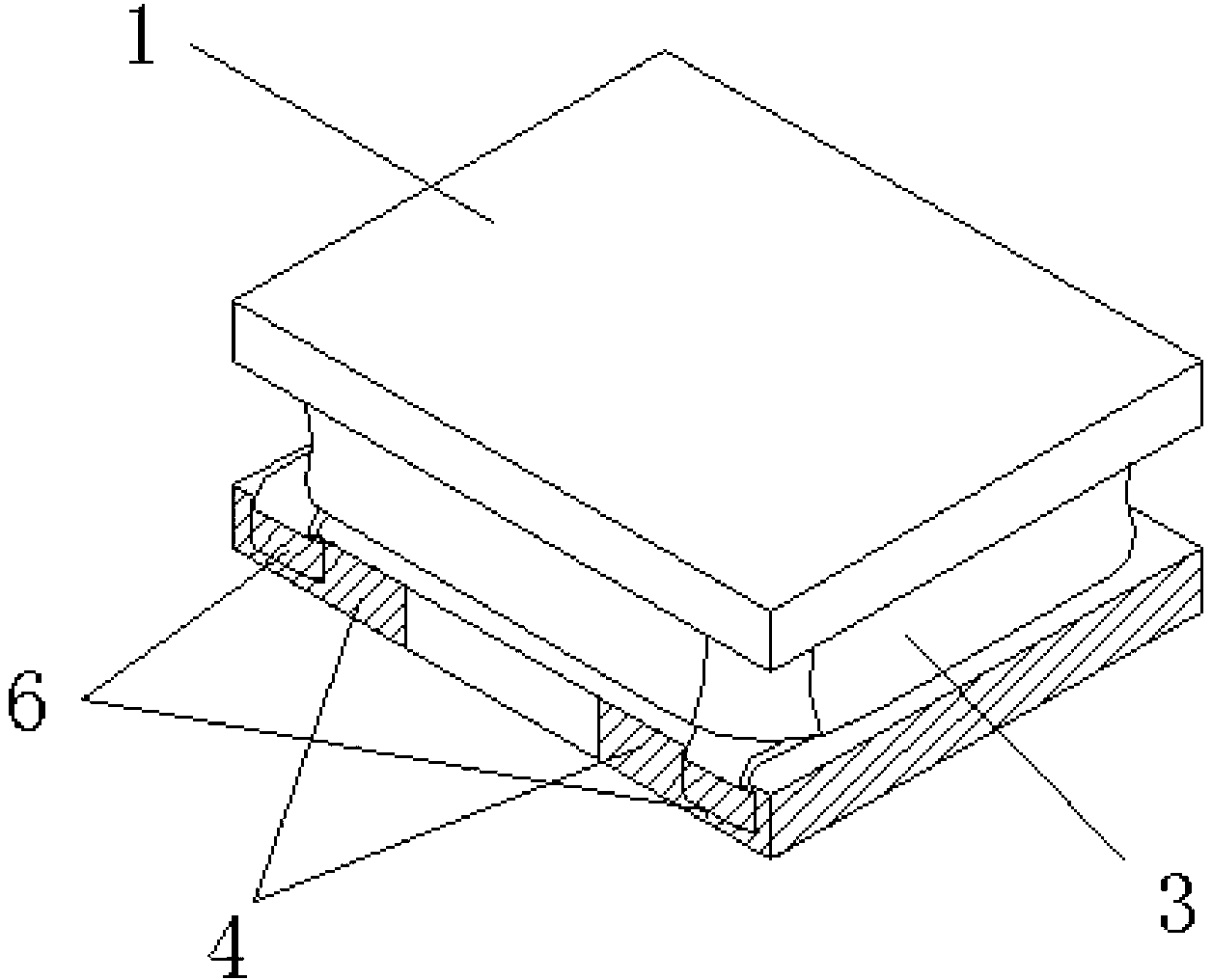
[0077] a kind of like Figure 1~3 The wire-wound power inductive element shown is an I-shaped wire-wound glue-coated power inductive element, which includes an I-shaped magnetic core 1 , a coil winding and an adhesive layer 3 on the surface.

[0078] The I-shaped magnetic core 1 is a magnetic core made of iron-silicon-chromium (FeSiCr) alloy powder with a particle size of 5 μm to 15 μm produced by the commercially available water atomization method, and its saturation magnetic flux density is significantly higher than that of the currently used nickel-zinc-iron The oxygen core can increase the saturation current of the power inductive element as much as possible under the condition that the inductance value of the power inductive element is constant.

[0079] The coil winding is a pair-wound flat enameled wire winding 2 made of a flat wire pair-wound method. In the limited and predetermined winding space required for miniaturization, wires with a larger conductor cross-section...

specific Embodiment approach 2

[0101] a kind of like figure 1 , 4 The wire-wound power inductive element shown in ~5 is basically the same as the specific embodiment 1, the difference lies in the following differences in its manufacturing method:

[0102] Step 2) The way of making the winding to wind the flat enameled wire winding is that the wire tail is close to the long side of the L-shaped sputtering metallization layer.

[0103] Step 3) Ultrasonic welding is used for the welding electrode, which is to weld and connect the tail of the flat enameled wire winding with the welding point on the long side of the L-shaped metallization layer to form an electrode.


PUM

PropertyMeasurementUnit
particle diameteraaaaaaaaaa
densityaaaaaaaaaa
thicknessaaaaaaaaaa

Abstract

Disclosed are a winding power inductor and a production method thereof. An I-shaped core is made of ferrous alloy soft magnet powder. A coil winding is a butt-wound flat enameled wire winding made by butt-welding flat wires. A glue layer is a magnetic glue layer made of ferrous alloy soft magnet and epoxy resin system. The production method includes: making the I-shaped core of the ferrous alloy soft magnet powder, making an L-shaped sputtered metallized layer on the vane swing side of the I-shaped core by means of sputtering, winding the flat enameled wires on a middle post of the I-shaped core by means of butt welding to make the butt-wound flat enameled wire winding, connecting wire ends of the butt-wound flat enameled wire winding to the L-shaped-section metallized layer by spot welding to form electrodes, and using a glue dispenser to coat the surface of the butt-wound flat enameled wire winding after the wire ends are fused so as to make the magnetic glue layer. The winding power inductor has the advantages of evident high current and low-current impedance, is simple in process, and is convenient for automatic batch production.

Description

technical field [0001] The invention relates to an inductance element, in particular to a wire-wound power inductance element and a manufacturing method thereof. Background technique [0002] The existing I-shaped winding glue-coated power inductor with a high degree of automation has a main frame made of nickel-zinc ferrite with a low saturation magnetic flux density, and the enameled wire is a round enameled wire with a low space utilization rate, which is difficult to While maintaining the corresponding inductance value in a smaller volume, it can withstand a larger current. Contents of the invention [0003] A technical problem to be solved by the present invention is to provide a wire-wound power inductive element to remedy the above-mentioned defects of the prior art. [0004] Another technical problem to be solved by the present invention is to remedy the defects of the above-mentioned prior art, and provide a manufacturing method of a wire-wound power inductive el...

Claims


Application Information

Patent Timeline
Patent Type & Authority Applications(China)
IPC IPC(8): H01F17/04H01F27/24H01F1/147H01F27/28H01F27/32H01F41/00H01F41/02H01F41/04
Inventor 夏胜程侯勤田
Owner 贵阳顺络迅达电子有限公司
Why Eureka
Try Eureka