Method for obtaining sulfur from sulfur compounds in coal chemical plant and electric power plant

A technology of sulfide and coal chemical industry, applied in the direction of sulfur preparation/purification, etc., can solve the problems of low economic value of recovered products, high total emission, and poor performance, etc., and achieve low construction cost and high sulfur recovery efficiency High, no secondary pollution effect

Active Publication Date: 2013-09-25
JIANGSU HENGXIN ENERGY TECH
View PDF5 Cites 10 Cited by
  • Summary
  • Abstract
  • Description
  • Claims
  • Application Information

AI Technical Summary

Problems solved by technology

For the control of sulfur dioxide, the "limestone-gypsum method" or "ammonia desulfurization" process is currently used. This technology is widely used, but the treatment efficiency is not high, and the value of the recyclables is not high, which will cause secondary pollution.
[0005] At present, coal chemical enterprises use two sets of independent devices to

Method used


Image

  • Method for obtaining sulfur from sulfur compounds in coal chemical plant and electric power plant
  • Method for obtaining sulfur from sulfur compounds in coal chemical plant and electric power plant

Examples


Embodiment 1

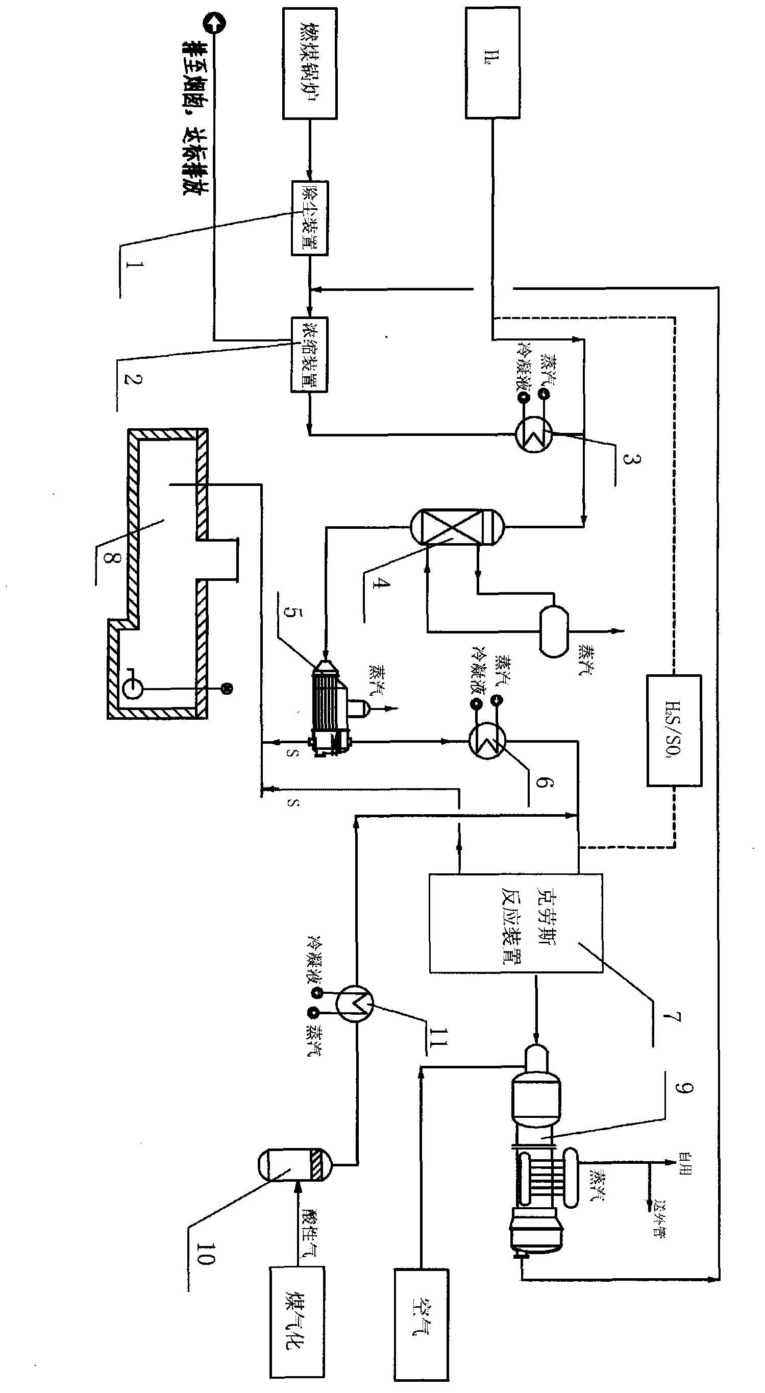
[0029] Example 1: as figure 1 As shown, the present invention comprises the following steps:

[0030] (1) The flue gas from the coal-fired boiler system passes through the dust removal device 1 and then enters the concentration device 2 for concentration treatment to increase the content of sulfur dioxide in the flue gas.

[0031] (2) The concentrated flue gas is heated by the flue gas preheater 3 and then enters the constant temperature selective reduction reactor 4, and the additional hydrogen is used as a reducing agent to react under the action of the selective reduction catalyst to generate elemental sulfur, The chemical equation is:

[0032] H 2 +SO 2 =S+H 2 O ①

[0033] The heat of the 2.1-2.6MPaG steam generated by the reaction is taken away by the cooling coil arranged in the thermostatic selective reduction reactor 4, so that the temperature of the thermostatic selective reduction reactor 4 is maintained at about 230°C.

[0034] (3) The catalytically reduced fl...

Embodiment 2

[0036] Embodiment 2: The difference from Embodiment 1 is:

[0037] In the step (3), what enters the Claus reaction device 7 also includes preheated coal gasification acid gas, and the acid gas enters the acid gas preheater 11 after gas separation in the acid gas separation tank 10 After heating, it enters the Claus reaction device 7 .

Embodiment 3

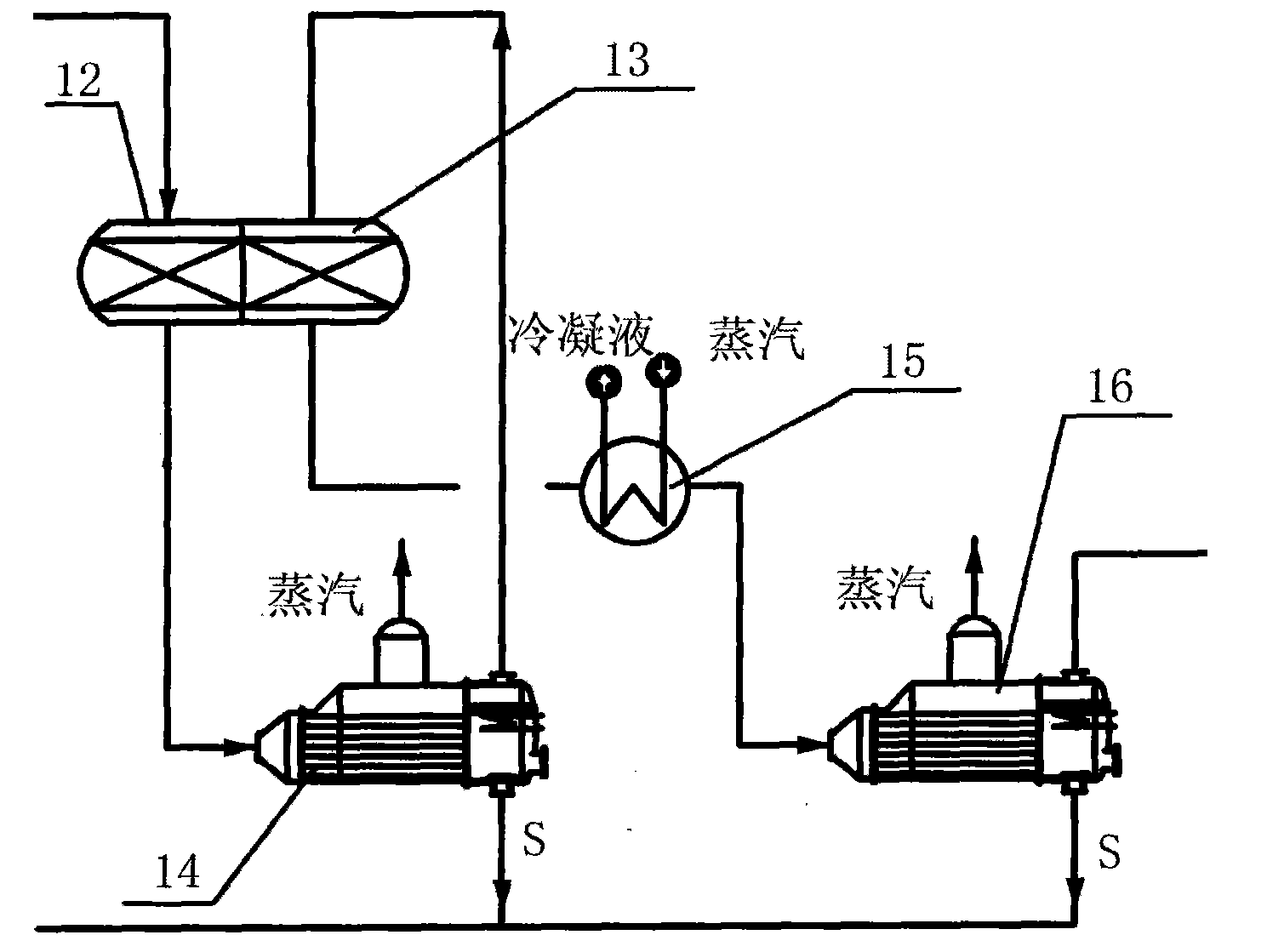
[0038] Example 3: The difference from Example 1 is:

[0039] The Claus reaction device 7 includes a primary Claus reactor 12, a secondary Claus reactor 13, a primary sulfur condenser 14, a secondary sulfur condenser 15 and a secondary reheater 16; The first-stage Claus reactor 12 and the second-stage Claus reactor 13 are filled with high-efficiency and active catalysts, and the catalytically reduced flue gas first enters the first-stage Claus reactor 12 for catalytic reaction, and then enters a first-stage Claus reactor 12 for catalytic reaction. The secondary sulfur condenser 14, the liquid sulfur that is removed enters the liquid sulfur pool and the flue gas enters the secondary Claus reactor 13 to continue the catalytic reaction, and the flue gas after the secondary catalytic reaction enters the secondary reheater 16 and then enters the secondary sulfur Condenser 15, the liquid sulfur removed by condensation treatment enters the liquid sulfur pool 8.


PUM


Abstract

The invention relates to a method for obtaining sulfur from sulfur compounds in a coal chemical plant and an electric power plant. The method comprises the following steps of: (1) dedusting exhaust gas from a coal burning boiler system, and then concentrating the exhaust gas to improve the content of sulfur dioxide in the exhaust gas; (2) heating the concentrated exhaust gas through an exhaust gas preheater, then introducing the exhaust gas into a constant temperature selective reduction reactor, and enabling the exhaust gas to react under the action of a selective reduction catalyst by adding hydrogen as a reducing agent so as to generate elemental sulfur, wherein the chemical equation is H2+SO2=S+H2O (1), and the heat generated by the reaction is taken away by a cooling coil which is arranged in the constant temperature selective reduction reactor to ensure that the temperature in the constant temperature selective reduction reactor is maintained at around 210-240 DEG C; (3) removing liquid sulfur from the exhaust gas subjected to catalytic reduction through a sulfur condenser, and introducing the exhaust gas into a Claus reaction device, wherein the liquid sulfur enters a liquid sulfur tank; and (4) burning the sulfur and sulfide contained in the tail gas passing through the Claus reaction device by using a combustion furnace so as to convert the sulfur and sulfide into sulfur dioxide, delivering the sulfur dioxide into the boiler system to mix with a dedusted process gas, and concentrating the mixture, wherein the gas discharged during concentration is mainly carbon dioxide.

Description

technical field [0001] The invention relates to a method for extracting sulfur, in particular to a method for obtaining sulfur from sulfide-containing substances in coal chemical industry and power plants. Background technique [0002] Coal chemical industry refers to an industrial process in which coal is used as a raw material for chemical processing into gases, liquids and solids and further processed into a series of chemical products. The operation of coal chemical plant must rely on huge power consumption, so in the process of coal chemical construction, enterprises often need to invest in preparing to build their own power plants. [0003] In the process of coal gasification and hydrogasification, the sulfur element contained in coal and hydrogen generate hydrogen sulfide, and the gasification gas needs to be desulfurized and decarbonized to synthesize various chemical products. The current desulfurization and decarbonization is a physical method, such as Low tempera...

Claims


Application Information

Patent Timeline
IPC IPC(8): C01B17/04
Inventor 邵志辉
Owner JIANGSU HENGXIN ENERGY TECH
Why Eureka
Try Eureka