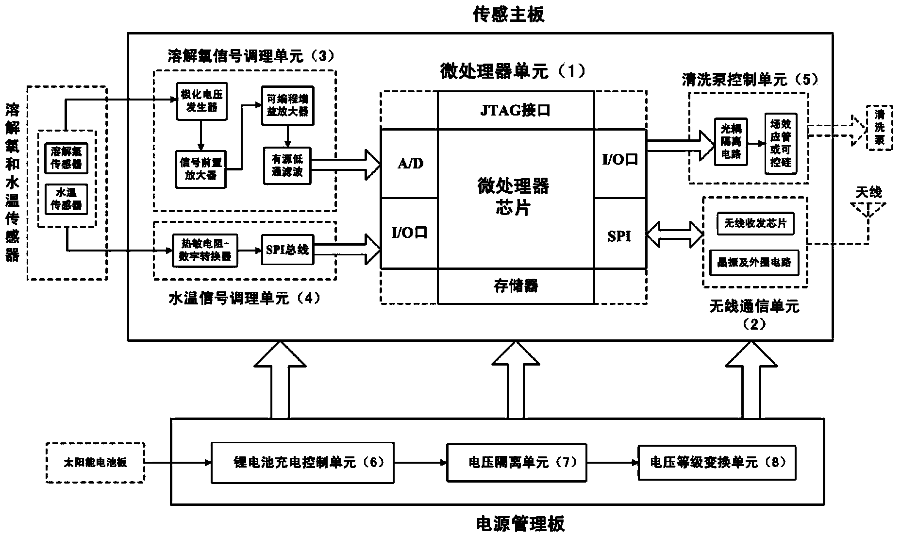
Aquaculture wireless sensor network node device and operation method
A wireless sensor and network node technology, which is applied in network topology, wireless communication, measurement devices, etc., can solve the problems of high price, inconvenient maintenance, and difficult to popularize and use in aquaculture waters, and achieves low cost, long life and good real-time performance. Effect
- Summary
- Abstract
- Description
- Claims
- Application Information
AI Technical Summary
Problems solved by technology
Method used
Image
Examples
Embodiment 1
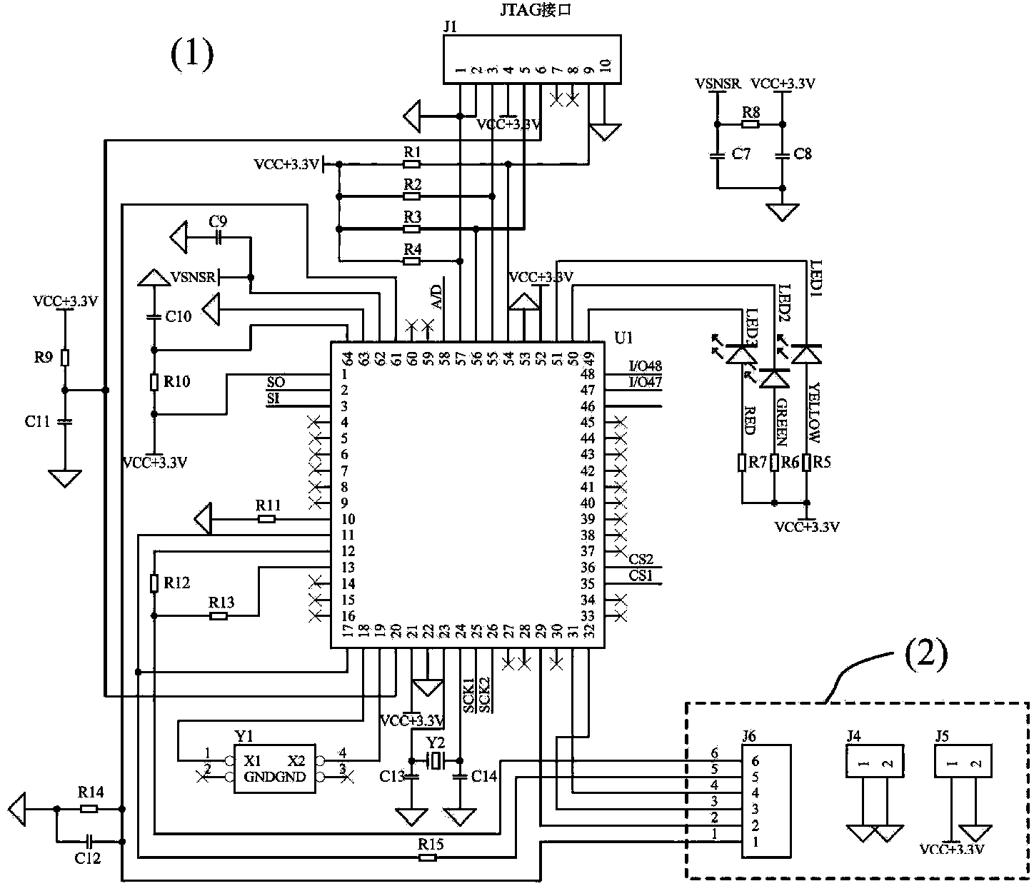
[0090] The microprocessor chip U1 in the above-mentioned microprocessor unit 1 selects the 8-bit CMOS processor ATmega128L of low power consumption and high performance produced by ATMEL Company, as figure 2 shown. ATmega128L is based on AVR RISC structure, and the data throughput rate is as high as 1MIPS / MHz, which can alleviate the contradiction between power consumption and processing speed of the system. The data lines of the JTAG interface in the microprocessor unit 1 are connected to the pins "54-57" of the ATmega128L microprocessor chip after passing through pull-up resistors "R1-R4". LED1-LED3 are the working state indicators of the ATmega128L microprocessor chip and the wireless communication unit 2 data sending and receiving indicators. In the system debugging stage, the running status of the program is judged according to the status of the indicators. The status indicators LED1-LED3 are the same as the " 49, 50, 51" pins are connected. R 9 with C 11Form a softw...
Embodiment 2
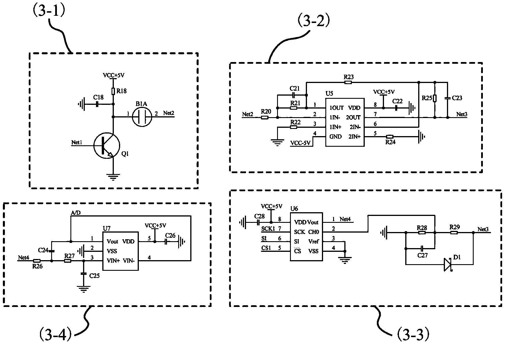
[0092] In the above-mentioned dissolved oxygen signal conditioning unit 3, the polarization voltage generator 3-1 is composed of an NPN transistor S8050 and an external resistor R 18 composition to obtain a stable 0.7V polarizing voltage output, such as image 3 shown. U5 is a precision dual operational amplifier TLC277ID, which has a wide range of low offset voltage input and drift, high input impedance, and low noise. Dual power supply mode is adopted, and the working voltage is reversed by the CMOS voltage inverter to supply power to TLC277ID. The voltage output by the signal preamplifier 3-2 is proportional to the current input by the dissolved oxygen signal conditioning unit 3, and the amplification factor By adjusting the external resistor R 25 The resistance value is obtained. The voltage signal output by the signal preamplifier 3-2 passes through the precision resistor R 28 and R 29 After the voltage is divided, the standard voltage signal is generated and input t...
Embodiment 3
[0097] In the above cleaning pump control unit 5, the "48" pin in the microprocessor chip U1 passes through the current limiting resistor R 16 It is connected to the "3" pin of U2. U2 uses an optocoupler isolation chip 6N137 to isolate the digital circuit and the analog circuit in the electrical space, avoiding various electrical interferences, such as Figure 5 shown. The "48" pin of the microprocessor chip U1 is connected to the gate G pin of the field effect transistor Q5 on the power management board. Q5 uses a power field effect transistor IRF7832. The cleaning pump automatically cleans the electrodes of the dissolved oxygen sensor. The opening and running time of the cleaning pump are realized by the microprocessor chip through software programming, which reduces human intervention.
PUM
 Abstract
Description
Claims
Application Information
 - R&D
- Intellectual Property
- Life Sciences
- Materials
- Tech Scout
- Unparalleled Data Quality
- Higher Quality Content
- 60% Fewer Hallucinations
Browse by: Latest US Patents, China's latest patents, Technical Efficacy Thesaurus, Application Domain, Technology Topic, Popular Technical Reports.
© 2025 PatSnap. All rights reserved.Legal|Privacy policy|Modern Slavery Act Transparency Statement|Sitemap|About US| Contact US: help@patsnap.com


