Eccentric engine using magnetic suspension object system time at same point in vertical surface

A technology of system timing and magnetic levitation, which is applied in the direction of engines, machines/engines, mechanical equipment, etc., and can solve the problems of large projects and high costs

Inactive Publication Date: 2013-10-16
袁海洋 +1
View PDF0 Cites 2 Cited by
  • Summary
  • Abstract
  • Description
  • Claims
  • Application Information

AI Technical Summary

Problems solved by technology

[0002] There are roughly two types of existing engines from energy conversion, one is to consume material energy (such as internal combustion engines, nuclear power reactors), but accompanied by pollution, but the principle i...

Method used


Image

  • Eccentric engine using magnetic suspension object system time at same point in vertical surface
  • Eccentric engine using magnetic suspension object system time at same point in vertical surface
  • Eccentric engine using magnetic suspension object system time at same point in vertical surface

Examples


Embodiment approach 1

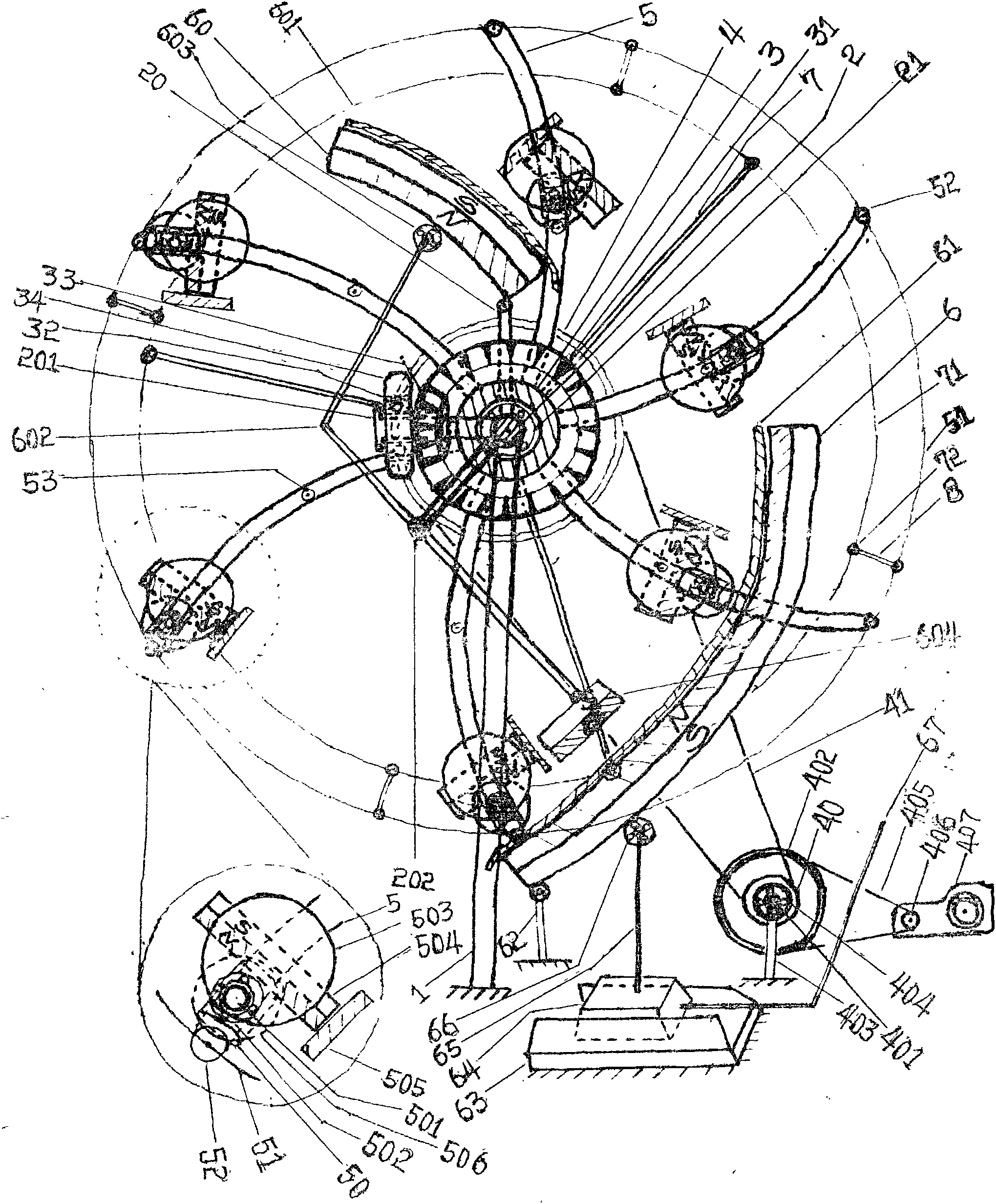
[0100] Embodiment 1, such as figure 1 Shown, the present invention comprises six major mechanisms by means of the eccentric motor at the same point in the vertical plane at all times by means of the magnetic levitation object system.

[0101] Slider action synchronous mechanism: the "parallel and opposite" slide bar 5 equipped with two rotating sleeves 3 on the same circumference of the single machine is equipped with a 50-action "synchronous" mechanism. The main bevel gear 31 is to mesh with the respective auxiliary bevel gear 32, which is conjoined with the auxiliary bevel gear 32 and coaxial with two straight (or helical) gears 34 that are just meshed, and on the same circumference in the middle of the outer surfaces of the two rotating sleeves 3, The sliding fitting 50 fitted on the sliding rod 5 of the inlaid pliers, and the horizontal rod 501 connected by the sliding fitting 50 on the sliding rod 5 with the same shape and the same arrangement posture of the two swivel sl...

Embodiment approach 2

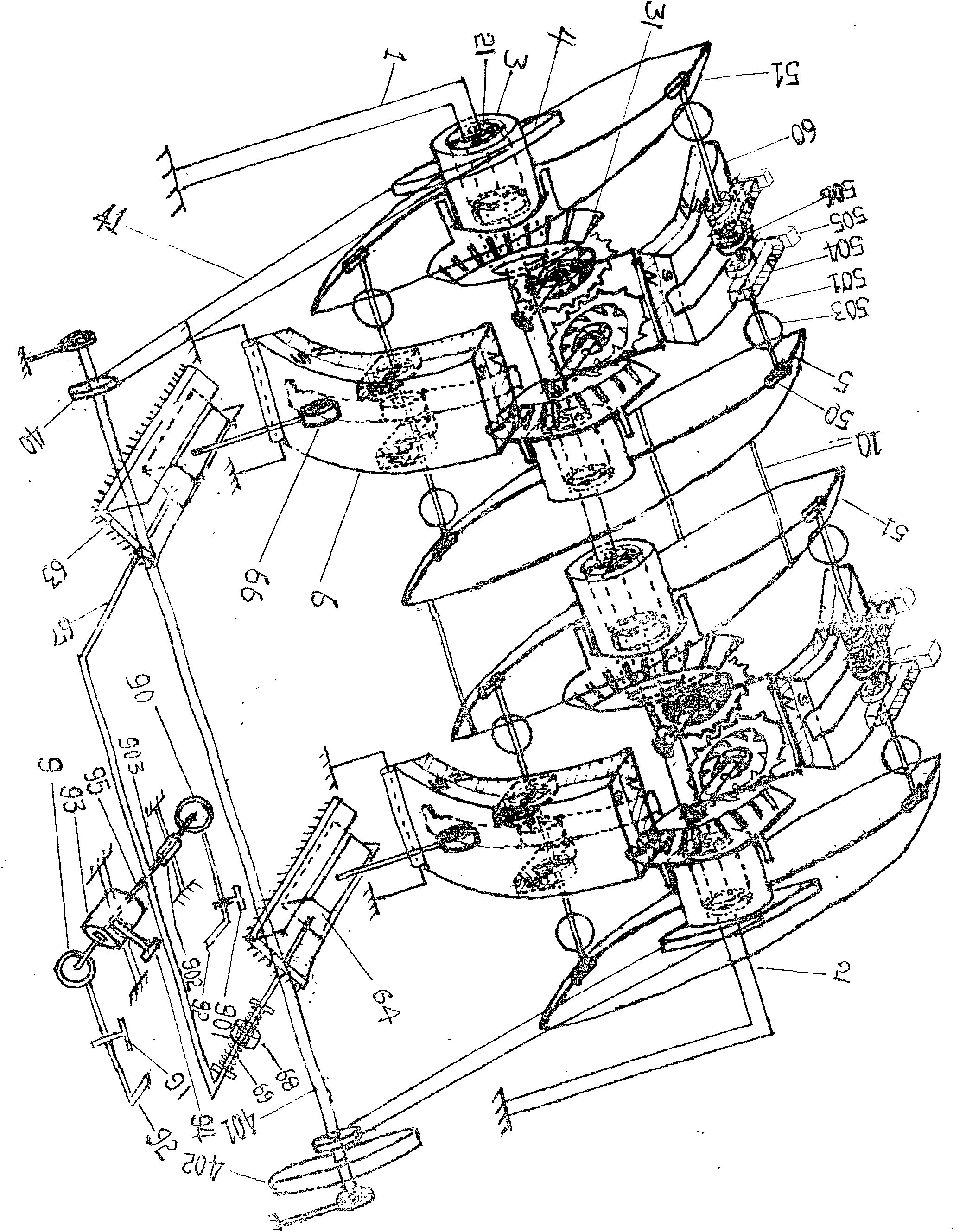
[0104] Implementation mode two: if figure 2 As shown, the "multi-unit linkage" mechanism of the present invention includes a plurality of stand-alone machines sharing an inverted "U"-shaped bracket at the same point in the vertical plane by means of the magnetic levitation object system at all times. The same two rotary sleeves 3 assemblies of multiple single machines are connected in series on the horizontal support 2, and the adjacent two single machines can only have the slide bar 5 on one side, and the closed circular metal rod 51 fixedly connected by the outermost end uses a cross bar 10 Come to Gulian. and share a power take-off shaft 401.

[0105] The operation control mechanism includes the driven wheel of the automatic transmission 407, which is driven by a belt to drive the "air compressor". "Air duct normally closed switch 91, then to the "start" air pump 9, the start air pump 9 drives the traction guide rod 95 that is sleeved in the fixed sliding sleeve 93, and ...

Embodiment approach 3

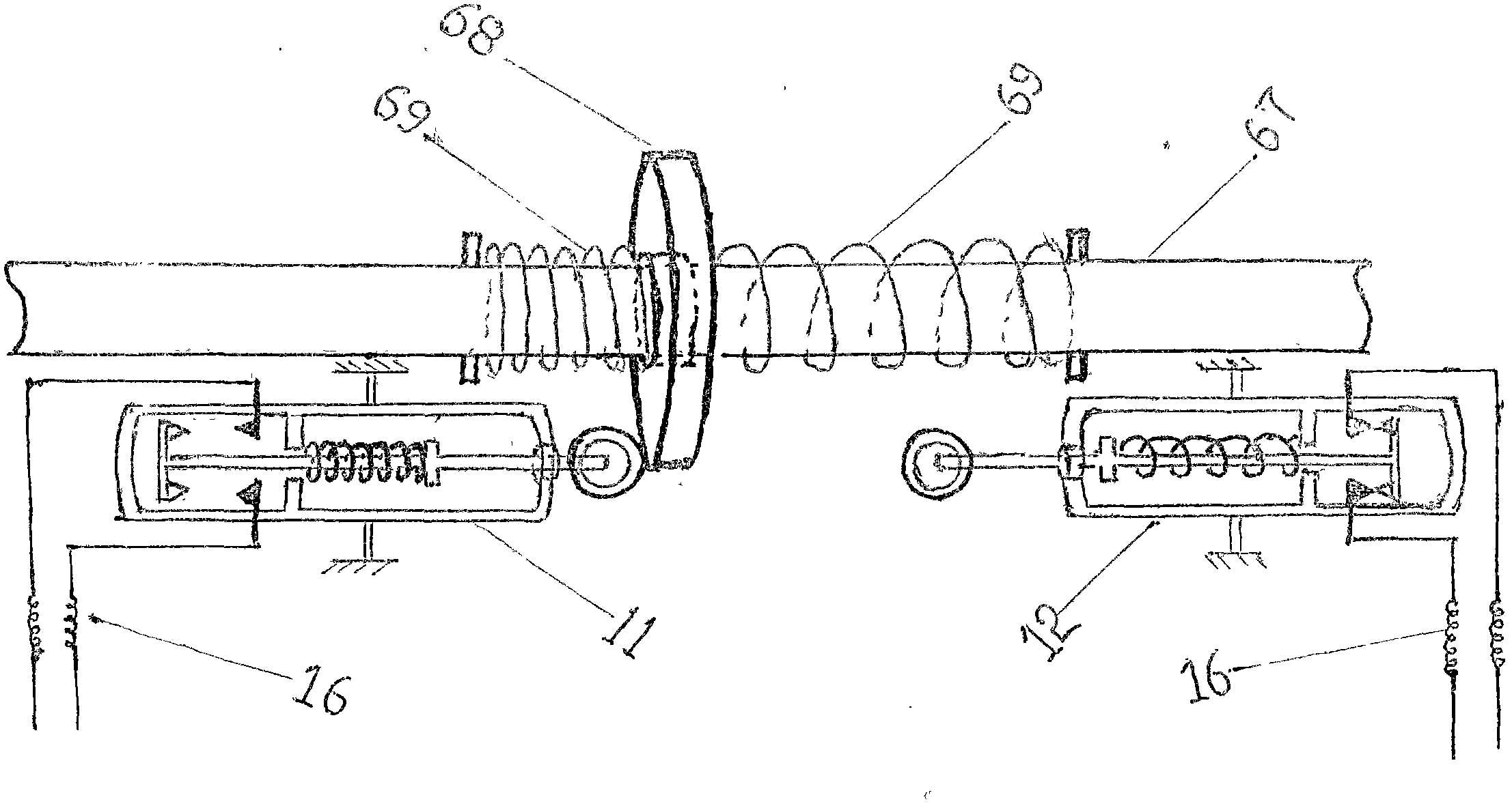
[0107] Embodiment 3; if image 3 and 4As shown, the present invention is eccentric at the same point in the vertical plane by means of the operation control mechanism of the eccentric motor at all times of the magnetic levitation object system. Including electronically controlled air pressure, and air pressure control operation (start up or stop operation). First, after the electric control electromagnet 13 is energized, the locking pin 94 of the armature conjoined body is completely separated from the starting traction guide rod 95, and after the dynamic and static contacts (14 and 15) on the electromagnet 13 are in contact, the starting valve 9 circuit is started again. Or shut down the air valve 90 circuit to make it work, and then move through the sliding assembly (trigger slide block) 68 set on the pneumatic guide rod 67 to trigger the travel switch 11 of the air pump 9 circuit that is controlled to start or to control the stroke of the air pump circuit 90 that is shut d...


PUM


Abstract

The invention relates to an eccentric engine using a magnetic suspension object system time at the same point in a vertical surface in order to solve the problem that the gravity of an object can not be converted into rotation moment to be output. The eccentric engine using the magnetic suspension system time at the same point in the vertical surface comprises two rotation sleeves assembled on a horizontal supporting frame at intervals, wherein identical bevel pinion sets are fixedly arranged at the inner sides of the two rotation sleeves, each sub-bevel pinion is connected with a pair of meshed gears and is assembled on a connected small shaft perpendicular to the horizontal supporting frame, a plurality of sets of sliding rods of the same shape (such as bent, straight and inclined) are evenly and fixedly installed on the same periphery of the surface of each rotation sleeve, a sliding matching part is arranged on each sliding rod in a matched mode, the sliding matching parts which are parallel and right face the sliding rods on the two rotation sleeves are connected through a horizontal rod with an idler wheel, a balance weight and a highly strong magnet connected in the middle, the outer ends of the sliding rods of each rotation sleeve are fixedly connected together, a highly strong magnet rail is fixedly arranged in a symmetrical dual-quadrant of the vertical surface between the rotation sleeves, the upper portion of the highly strong magnet rail is shaped like an involute and is located under the horizontal rod, and the lower portion of the highly strong magnet rail is shaped like an involute and is located above the horizontal rod. A plurality of sets of engines are connected in series on the horizontal frame at intervals, and the eccentric engine using the magnetic suspension system time at the same point in the vertical surface is a large-power engine converting the gravity into power.

Description

technical field [0001] The invention relates to an engine, in particular to an eccentric engine at the same point in a vertical plane at all times by means of a magnetic levitation object system. Background technique [0002] There are roughly two types of existing engines from energy conversion, one is to consume material energy (such as internal combustion engines, nuclear power reactors), but accompanied by pollution, but the principle is scientific, the structure is reasonable, and the process is complicated; the other is to use natural energy ( Such as wind turbines, water turbines, photovoltaic cells, tidal engines), but the cost is high and the project is large. As for the use of the gravity of solid objects to convert power machinery, it has not yet come out, especially the mechanical efficiency is high, the structure is simple, easy to implement, the cost is low, the action is reliable, no noise, especially high-power no material energy consumption, no pollution "gr...

Claims


Application Information

Patent Timeline
IPC IPC(8): F03G3/00H02N15/00
Inventor 袁海洋袁海江
Owner 袁海洋
Why Eureka
Try Eureka