Spring type nanometer generator and self-driven dynamometer

A nano-generator and spring-type technology, which is applied in the direction of generator/motor, the measurement of the force of the piezoelectric device, the piezoelectric effect/electrostrictive or magnetostrictive motor, etc., which can solve the inconvenience of normal operation of the components , Low mechanical strength, application limitations, etc., to achieve the effect of miniaturization, expanded application range, and high mechanical strength

Active Publication Date: 2013-10-16
BEIJING INST OF NANOENERGY & NANOSYST
View PDF4 Cites 11 Cited by
  • Summary
  • Abstract
  • Description
  • Claims
  • Application Information

AI Technical Summary

Problems solved by technology

However, the existing self-driven pressure sensors are all flat thin-layer devices. Although the size is small, the mechanical strength is not high, the upper limit of the pressure source that can withstand is low, and it always needs to be fixed on some mechanical devices in a certain way. components or other devices, which may cause inconvenience to the normal operation of these components, so it is subject to certain restrictions in application
In addition, the stable correlation between the pressure source and the output signal is also a key issue restricting the application of pressure sensors.

Method used


Image

  • Spring type nanometer generator and self-driven dynamometer
  • Spring type nanometer generator and self-driven dynamometer
  • Spring type nanometer generator and self-driven dynamometer

Examples


Embodiment 1

[0082] Embodiment 1: spring type nanogenerator

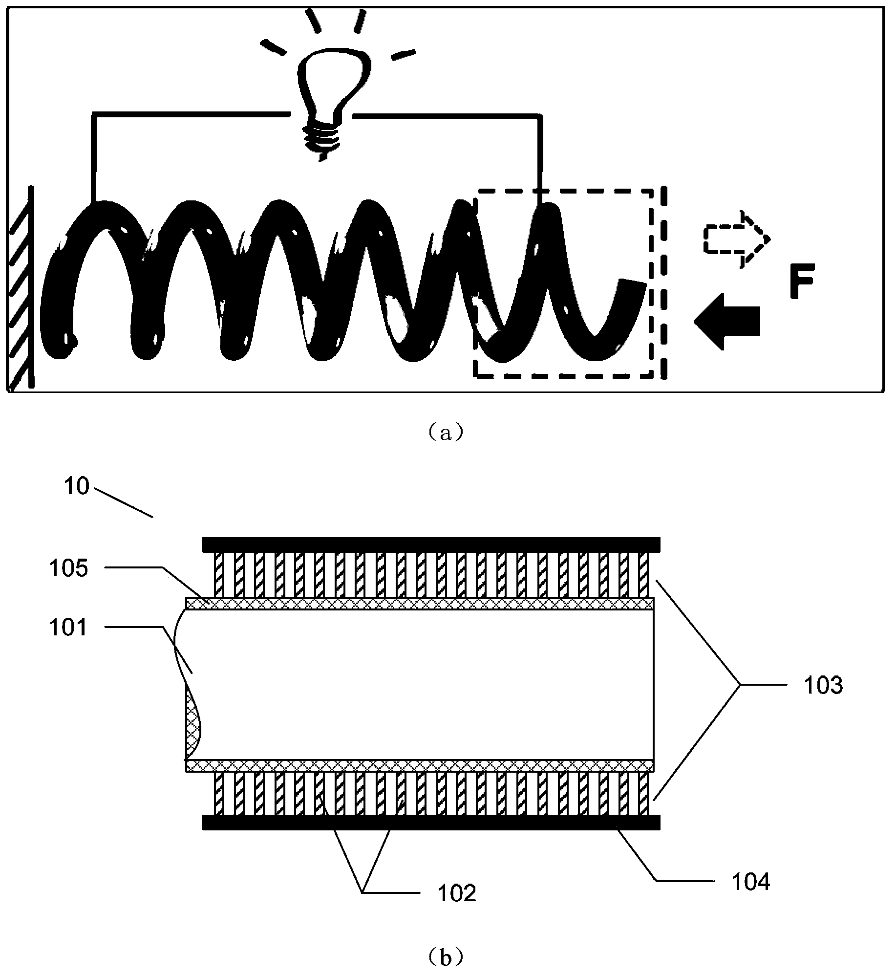
[0083] A copper spring with a length of 3.5 inches and a spring wire diameter of 0.028 inches is used as the substrate, and an array of closely arranged CdS nanorods is formed on its surface by in-situ preparation to form a piezoelectric layer. The gap of the rod array is filled with insulating material polyimide, and after cooling and solidification, an Au electrode layer is formed by sputtering on the outside of the piezoelectric layer. The spring-type nano generator of the present invention can be formed by connecting the Au electrode layer and the stainless steel wire with an external circuit.

Embodiment 2

[0084] Embodiment 2: the preparation method of spring type nanogenerator

[0085] Although the in-situ preparation of nano piezoelectric materials is a conventional method in the art, a typical method for preparing nanogenerators is still provided, so that those skilled in the art can understand the general process of preparing nanogenerators of the present invention, which is convenient The promotion and application of this technology: 1) Treat the surface of the stainless steel spring with 0.1mol / L dilute hydrochloric acid for 5 minutes to remove the oxide layer on the surface; 2) Coat the surface of the spring with a layer of zinc oxide seeds by sputtering or solution method layer (100-200nm); 3) Grow dense zinc oxide nanowire arrays on the surface of the sample by hydrothermal method. L, the reaction temperature is 95°C, and the reaction time is 5 hours; 4) After the reaction, the sample is taken out of the solution, dried, and coated with a polymethyl methacrylate insulat...

Embodiment 3

[0087] Embodiment 3: the measuring method of spring type nanogenerator

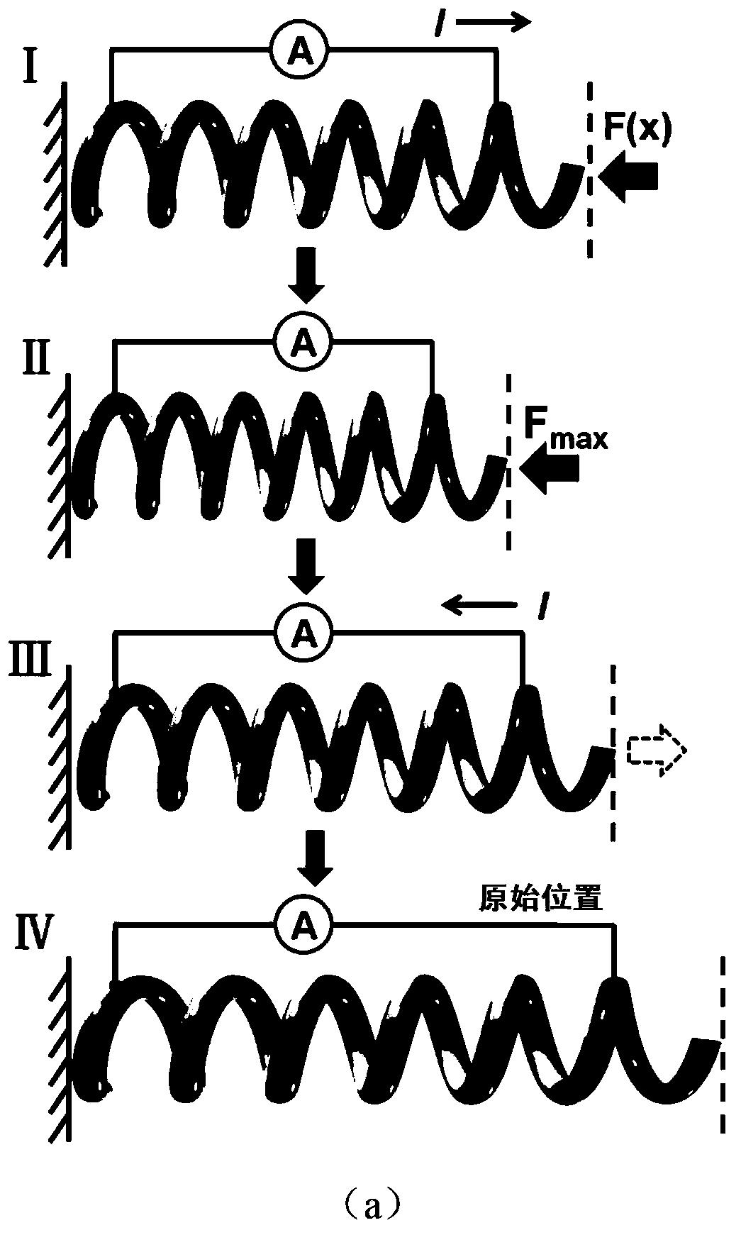
[0088] In order to measure the electrical signal output by the spring-type nanogenerator, the following methods can be used: 1) fix a square plastic plate (or other insulating materials) on the push rod of the linear motor; 2) place the spring-type nanogenerator Fix it on a vertical bracket so that the spring is perpendicular to the direction of the plastic plate; 3) Control the linear motor with a computer to compress the spring in a certain period; 4) Connect the lead wires from the inner and outer electrodes of the generator into the measuring device, and use The SR560 voltmeter of Stanford Research System was used to measure the open circuit voltage, and the SR570 ammeter was used to measure the short circuit current.

[0089] The output voltage and current data measured in the experiment are as follows Figure 8 As shown in -a and 8-b, it can be seen that under the action of periodic external force,...


PUM

PropertyMeasurementUnit
thicknessaaaaaaaaaa
thicknessaaaaaaaaaa
thicknessaaaaaaaaaa

Abstract

The invention provides a piezoelectric nanometer generator prepared by taking a spring as a base, and a self-driven dynamometer based on the nanometer generator. The spring type nanometer generator comprises a spring base, a conductive outer surface included by a spring wire forming the spring base, a piezoelectric body layer and an outer electrode, wherein the piezoelectric body layer is tightly contacted with the outer side of the conductive outer surface, and the outer electrode is tightly contacted with the outer side of the piezoelectric body layer. The piezoelectric body layer can generate a piezoelectric effect under the condition that deformation of the spring base occurs, and outputs electric signals to an external circuit through the conductive outer surface and the outer electrode. A self-driven pressure sensor and the measurement can be realized by using the advantage that the compression distance of the spring has a linear relation with an applied external force. The self-driven dynamometer provided by the invention is small in size, and can be arranged in various mechanical components conveniently; and the self-driven dynamometer does not need an external power supply during operation, and has the advantages of safety, reliability, environmental protection and the like, thereby being of great significance for sustainable development of intelligent transportation and modern industries.

Description

technical field [0001] The invention provides a spring-based piezoelectric nanogenerator, in particular a self-driven force measuring instrument based on the nanogenerator. Background technique [0002] The proposal and development of the concept of "wireless sensor network" is of great significance to the progress and development of today's society. A variety of different forms of sensors, including biological, chemical, gas, pressure, temperature, etc., can be used as the basic components of sensor networks. However, traditional sensor devices require an external DC power source (such as a battery) to drive the device, which adds a lot of burden and cost to the entire system, such as the cost of battery replacement and the increase in system weight of the battery itself. [0003] In recent years, the advent of self-driven pressure sensors based on piezoelectric nanogenerators has largely suggested a possible solution to this problem. The principle of this self-driven pre...

Claims


Application Information

Patent Timeline
Patent Type & Authority Applications(China)
IPC IPC(8): H02N2/18H01L41/113G01L1/16
Inventor 王中林林龙
Owner BEIJING INST OF NANOENERGY & NANOSYST
Why Eureka
Try Eureka