Method for preparing magnetic tunnel junction (MTJ) nano column array

A technology of nano-column array and bottom electrode, which is applied in the field of micro-nano electronics, can solve the problems of large experimental error and cumbersome and complicated preparation process, and achieve reduced experimental error, good etching resistance, and omission of coating and stripping processes Effect

Active Publication Date: 2013-10-23
HUAZHONG UNIV OF SCI & TECH
View PDF8 Cites 5 Cited by
  • Summary
  • Abstract
  • Description
  • Claims
  • Application Information

AI Technical Summary

Problems solved by technology

[0008] In view of the above defects or improvement needs of the prior art, the present invention provides a method for preparing an MTJ nanocolumn array, the purpose of which is to reduce process steps, greatly reduce costs, and reduce process errors, thereby solving the problem of the existing preparation process Complicated and complicated technical problems with large experimental errors

Method used


Image

  • Method for preparing magnetic tunnel junction (MTJ) nano column array
  • Method for preparing magnetic tunnel junction (MTJ) nano column array
  • Method for preparing magnetic tunnel junction (MTJ) nano column array

Examples


preparation example Construction

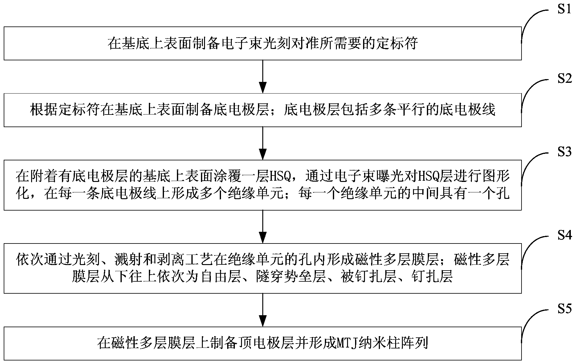
[0033] Such as figure 1 with figure 2 As shown, the preparation method of the MTJ nanocolumn array provided by the invention mainly includes the following steps:

[0034] S1: Prepare the calibration marks 12 required for electron beam lithography alignment on the upper surface of the substrate 1 by means of electron beam exposure, evaporation and stripping;

[0035] The scale marks can be multiple cross-shaped heavy metal marks, which play a vital role in the precise positioning of the device during the "overlay" process of several electron beam exposures; generally, there are 4 scale marks located on the substrate the four corners of the surface.

[0036]S2: Prepare the bottom electrode layer 3 on the upper surface of the substrate 1 according to the scale symbol 12. The bottom electrode layer 3 includes N parallel bottom electrode lines; the value of N is determined by the number of MTJ nanocolumns that have been set.

[0037] S3: Coating a layer of HSQ photoresist 13 on...

Embodiment 1

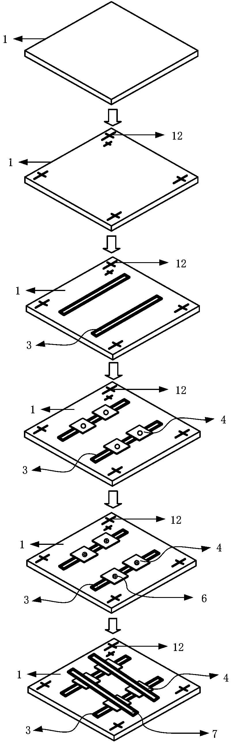
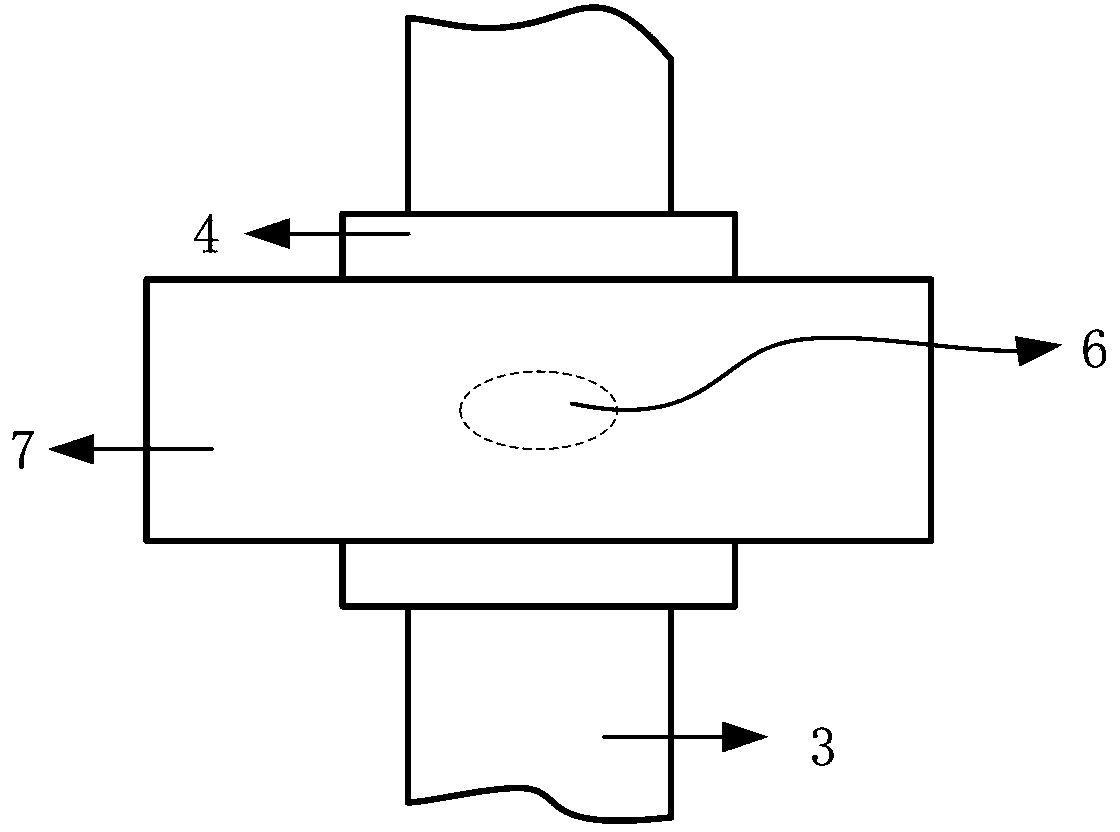
[0050] figure 2 The preparation process flow of MTJ nanocolumn array in embodiment 1 is shown, image 3 with Figure 4 They are a top view and a cross-sectional view of an MTJ nanocolumn in Example 1, respectively. refer to figure 2 , image 3 with Figure 4 The MTJ nanocolumn array in Embodiment 1 of the present invention includes a substrate 1 , a scale 12 , a bottom electrode layer 3 , an insulating unit 4 , a magnetic multilayer film layer 6 and a top electrode layer 7 . refer to Figure 5 , The magnetic multilayer film layer 6 includes a free layer 8 , a tunneling barrier layer 9 , a pinned layer 10 , and a pinned layer 11 from bottom to top.

[0051] Wherein, the base 1 is an insulating substrate, such as a ceramic substrate, a glass substrate, a resin substrate, a quartz substrate, and the like. The size and thickness of the substrate 1 are not limited, and those skilled in the art can select according to needs. In this embodiment, the material of the substrat...

Embodiment 2

[0108] Compared with Example 1, the coating method of the bottom electrode layer and the top electrode layer is changed, and other steps remain unchanged. Both the bottom electrode layer and the top electrode layer are prepared by electron beam evaporation.


PUM

PropertyMeasurementUnit
thicknessaaaaaaaaaa
pore sizeaaaaaaaaaa
pore sizeaaaaaaaaaa

Abstract

The invention discloses a method for preparing a magnetic tunnel junction (MTJ) nano column array. The method comprises the following steps of: (1) preparing a calibrator required for electron beam lithography alignment on the surface of a substrate; (2) preparing a bottom electrode layer on the upper surface of the substrate according to the calibrator, wherein the bottom electrode layer comprises a plurality of parallel bottom electrode lines; (3) coating a hydrogen silsesquioxane (HSQ) layer on the upper surface of the substrate to which the bottom electrode layer is attached, imaging the HSQ layer through electron beam exposure, and forming a plurality of insulation units on each bottom electrode line, wherein a hole is formed in the middle of each insulation unit; (4) forming a magnetic multi-layer film layer in the hole of each insulation unit sequentially through a lithography process, a sputtering process and a peeling process, wherein each magnetic multi-layer film layer sequentially comprises a free layer, a tunneling barrier layer, a pinned layer and a pinning layer from bottom to top; (5) preparing a top electrode layer on each magnetic multi-layer film layer and forming the MTJ nano column array. An insulation layer is formed by the electron beam exposure of HSQ, so that process steps are simplified, the cost is greatly reduced, and process errors are reduced.

Description

technical field [0001] The invention belongs to the technical field of micro-nano electronics, and more specifically relates to a method for preparing an MTJ nanocolumn array. Background technique [0002] In 1996, Slonczewski and Berger predicted through theoretical calculations that when a spin-polarized current flows through a nanometer-sized ferromagnetic thin film or metal magnetic multilayer film, the polarization current and the scattering in the multilayer film will bring about the polarized electrons The spin angular momentum transfer to the magnetic moment of the ferromagnetic film, thereby generating a spin moment to the magnetic moment of the ferromagnetic film, causing the imbalance of the magnetic moment of the ferromagnetic film, causing it to rotate, precess and even reverse the magnetization direction. This effect is called spin angular momentum transfer effect (Spin-Torque-Transfer, referred to as STT effect). [0003] Spin angular momentum transfer magnet...

Claims


Application Information

Patent Timeline
Patent Type & Authority Applications(China)
IPC IPC(8): B81C1/00
Inventor 刘辉程晓敏缪向水
Owner HUAZHONG UNIV OF SCI & TECH
Why Eureka
Try Eureka