Power plant carbon and oxygen circulation utilization device and process of device

A carbon-oxygen and power plant technology, applied in the chemical industry, petroleum industry, carbon monoxide, etc., can solve the problems of waste of CO2 and O2 resources, low thermal energy conversion rate, environmental pollution, etc., to improve the net conversion rate of thermal energy, reduce equipment investment, The effect of saving coal

Active Publication Date: 2013-12-18
浙江森井生物技术股份有限公司
View PDF7 Cites 13 Cited by
  • Summary
  • Abstract
  • Description
  • Claims
  • Application Information

AI Technical Summary

Problems solved by technology

[0008] In order to overcome the above-mentioned deficiencies, the present invention aims to provide a carbon-oxygen recycling device and a process thereof in a power plant, solve the problems of low thermal energy conversion rate, waste of CO2 and O2 resources, and pollute the environment in the existing power plant, and realize the carbon-oxygen recycling of the power plant. Improve heat conversion rate

Method used


Image

  • Power plant carbon and oxygen circulation utilization device and process of device
  • Power plant carbon and oxygen circulation utilization device and process of device
  • Power plant carbon and oxygen circulation utilization device and process of device

Examples


Embodiment 1

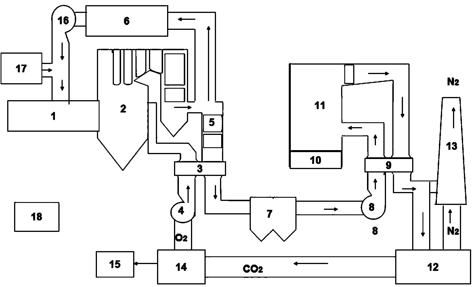
[0029] Embodiment 1: as figure 1 As shown, the carbon-oxygen recycling device of the power plant consists of a coal feeder 17, a CO2 return device 6, a plasma torch catalyst 1, an energy-saving boiler 2, a denitrification device 5, a heat exchanger 3, a dust collector 7, a booster fan 16, and an induced draft fan 8. Composed of desulfurization slag liquid 10, desulfurization tower 11, heat exchanger 9, CO2 capture separator 12, deoxidizer 14, blower 4, carbon recovery device 15, remote explosion-proof master control detection system 18, and chimney 13; the plasma One end of the torch catalytic converter 1 is connected to the coal feeder 17 and the CO2 reflux device 6, and the other end is connected to the flue gas inlet at the lower part of the energy-saving boiler 2. The lower part is also provided with a flue gas outlet, and the lower flue gas outlet is connected to the flue gas inlet flue of the heat exchanger 3; the flue gas outlet flue of the heat exchanger 3 is connected...

Embodiment 2

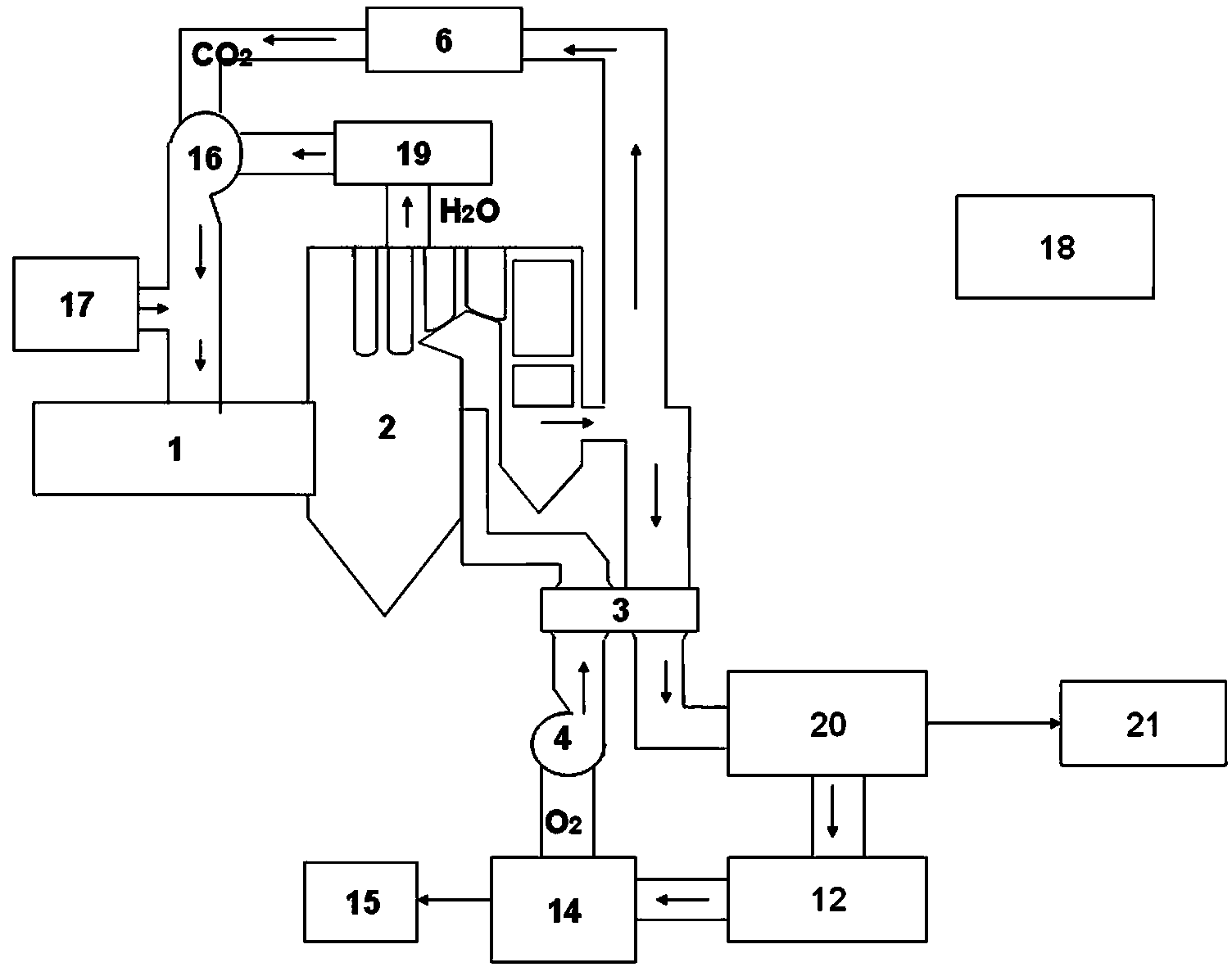
[0067] Embodiment 2: as figure 2 As shown, the carbon-oxygen recycling device of the power plant consists of a coal feeder 17, a CO2 return device 6, a plasma torch catalyst 1, an energy-saving boiler 2, a heat exchanger 3, a booster fan 16, a CO2 capture separator 12, and a deoxidizer 14 , blower 4, carbon recoverer 15, remote explosion-proof master control detection system 18, water vapor tank 19, purifier 20, sulfur-based compound fertilizer production line 21; one end of the plasma torch catalyst 1 is connected to the coal feeder 17, and the other end It is connected with the flue gas inlet at the lower part of the energy-saving boiler 2, the top of the energy-saving boiler 2 is provided with an outlet, and the outlet at the top is connected with the CO2 reflux device 6, the lower part of the energy-saving boiler 2 is provided with a flue gas outlet, and the lower flue gas outlet is connected with the heat exchanger 3 The flue gas inlet flue is connected; the water vapor ...


PUM


Abstract

The invention relates to the field of energy saving and environment protection, and relates to the circulation utilization of CO2 (carbon dioxide) and O2 (oxygen gas), in particular to a power plant carbon and oxygen circulation utilization device and a process of the device. The power plant carbon and oxygen circulation utilization device comprises a coal conveyor (17), a CO2 back flow device (6), a plasma torch catalyst (1), an energy-saving boiler (2), a heat exchanger (3), a CO2 catching separator (12), a deaerator (14), a remote anti-explosion total control detection system (18) and a chimney (13). A carrier air coal conveying mode is adopted for conveying reaction raw materials into the plasma torch catalyst (1) to be catalyzed, the catalyzed reaction substances are conveyed into the energy-saving boiler (2) to realize the sufficient combustion with O2, and the generated CO2 is cyclically utilized after the deoxygenation. The device and the process have the advantages that firstly, the low-cost pure oxygen combustion is realized; secondly, the CO2 backflow catalysis and deoxygenation circulation utilization is realized; thirdly, the equipment investment is reduced, and 70 to 80 percent of the equipment volume of the boilers in links of dust removal, denitration, desulfuration and the like is reduced; fourthly, 45 to 70 percent of the coal consumption is saved; and fifthly, the pure conversion rate of heat energy is improved by more than one time.

Description

technical field [0001] The invention relates to the field of energy conservation and environmental protection, and to the recycling of CO2 and O2, in particular to a carbon-oxygen recycling device and a process for a power plant. Background technique [0002] CO2, the main culprit of the greenhouse effect generated by power plants, is not conducive to the current environmental protection requirements. At the same time, the current traditional power plant technology has the following defects in addition to IGCC power generation: [0003] 1. Air combustion, the net conversion rate of heat energy is low, the main reaction formula is: C+O2+N2——CO2+N2; [0004] About 2.7 tons of O2 are needed to burn 1 ton of standard coal, and about 10 tons of N2 are brought in. In the combustion exhaust gas, the content of N2 is 78-85%, and the content of CO2 is only 8-15%. The high content of N2 in the flue gas is the direct cause of the low net conversion rate of heat energy, and the second ...

Claims


Application Information

Patent Timeline
Patent Type & Authority Applications(China)
IPC IPC(8): F23K3/02F23C9/00F23J15/02C10L3/00C01B31/18C01B32/40
CPCY02E20/32Y02P20/10
Inventor 程礼华
Owner 浙江森井生物技术股份有限公司
Why Eureka
Try Eureka