Method for forming inverted pyramid-shaped porous surface nano-texture on polysilicon and method for preparing short-wave enhanced solar cell
An inverted pyramid-shaped, porous surface technology, used in circuits, photovoltaic power generation, electrical components, etc., can solve problems such as limiting photoelectric conversion efficiency, and achieve high short-wave spectral response, low surface reflectivity, and low cost.
- Summary
- Abstract
- Description
- Claims
- Application Information
AI Technical Summary
Problems solved by technology
Method used
Image
Examples
Embodiment 1
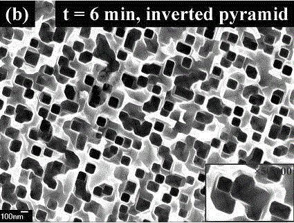
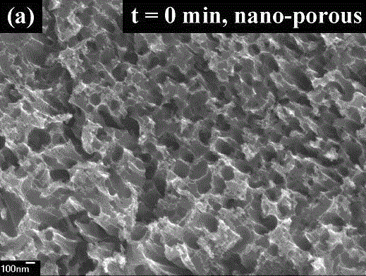
[0036] In this example, see Figure 1 to Figure 6 , a method for forming an inverted pyramid-shaped porous surface nanotexture on polysilicon, comprising the steps of:
[0037] (1) Use solar-grade polysilicon as the substrate material, which is P Type boron doping, the thickness is 200mm, the minority carrier lifetime is 2ms, and the resistivity is 3Ωcm; 3 h 6 O carry out 5 minutes ultrasonic cleaning to the silicon wafer as solar cell silicon substrate material, remove the organic residue on the surface of silicon wafer; 3 =(1:10), etch under the condition of 5°C, the reaction time is 3.5 minutes, so as to remove the mechanical damage layer on the surface of the silicon wafer, and its cross-sectional structure is shown in figure 1 , surface reflectance see Figure 4 ;
[0038] (2) Then, the silicon wafer is immersed in 0.004mol / LHF and 0.32mol / LAgNO 3 In an aqueous solution, react at room temperature for 15-20 seconds to deposit nano-silver particles on its surface; sil...
Embodiment 2
[0043] This embodiment is basically the same as Embodiment 1, especially in that:
[0044] In this example, see Figure 5 and Figure 6 , the nb-Si material sample was first immersed in dilute HF solution to remove its surface oxide layer, and then immediately immersed in 1% NaOH etching solution, the reaction time was 3 minutes, and the reaction temperature was room temperature. from Figure 5 It can be seen that in the wavelength range of 580-1000 nm, the surface reflectance of the IP-Si battery of this embodiment is lower than that of the nb-Si battery of Comparative Example 2. from Figure 6 It can be seen that the nb-Si of Comparative Example 2 and the IP-Si battery of this embodiment EQE Curves and calculated photogenerated current densities J sc : respectively 24.8mA / cm 2 and 31.6mA / cm 2 , the photogenerated current density of the IP-Si battery of this embodiment is higher than that of the nb-Si battery of Comparative Example 2.
Embodiment 3
[0046] This embodiment is basically the same as Embodiment 1, especially in that:
[0047] In this example, see Figure 5 and Figure 6 , the nb-Si material sample was first immersed in dilute HF solution to remove its surface oxide layer, and then immediately immersed in 1% NaOH etching solution, the reaction time was 9 minutes, and the reaction temperature was room temperature. from Figure 5 It can be seen that in the wavelength range of 580-1000 nm, the surface reflectance of the IP-Si battery of this embodiment is lower than that of the nb-Si battery of Comparative Example 2. from Figure 6 It can be seen that the nb-Si of Comparative Example 2 and the IP-Si battery of this embodiment EQE Curves and calculated photogenerated current densities J sc : respectively 24.8mA / cm 2 and 32.8mA / cm 2 , the photogenerated current density of the IP-Si battery of this embodiment is higher than that of the nb-Si battery of Comparative Example 2.
PUM
| Property | Measurement | Unit |
|---|---|---|
| thickness | aaaaa | aaaaa |
| thickness | aaaaa | aaaaa |
| thickness | aaaaa | aaaaa |
Abstract
Description
Claims
Application Information
 - R&D
- Intellectual Property
- Life Sciences
- Materials
- Tech Scout
- Unparalleled Data Quality
- Higher Quality Content
- 60% Fewer Hallucinations
Browse by: Latest US Patents, China's latest patents, Technical Efficacy Thesaurus, Application Domain, Technology Topic, Popular Technical Reports.
© 2025 PatSnap. All rights reserved.Legal|Privacy policy|Modern Slavery Act Transparency Statement|Sitemap|About US| Contact US: help@patsnap.com


