
Combined type energy-saving gas turbine inlet air cooling system

A gas turbine and intake air cooling technology, which is applied to gas turbine devices, jet propulsion devices, mechanical equipment, etc., can solve the problems that the air temperature cannot reach the ambient wet bulb temperature, the limited effect in high temperature and high humidity areas, and the low operation and maintenance costs. Achieve the effect of reducing one-time investment and operating costs, reducing installed capacity and reducing energy consumption

Active Publication Date: 2013-12-25
无锡金龙石化冶金设备制造有限公司
View PDF7 Cites 20 Cited by
  • Summary
  • Abstract
  • Description
  • Claims
  • Application Information

AI Technical Summary

Problems solved by technology

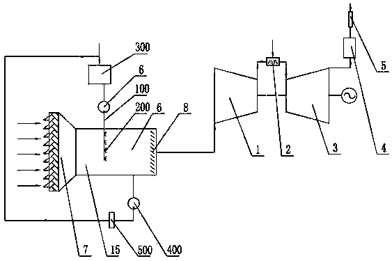
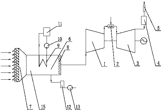
At present, there are two main ways to cool the intake air of gas turbines: first, spray direct evaporative cooling, that is, in the intake passage of gas turbines, high-pressure desalted water passes through atomizing nozzles to form sprays and mixes with air, evaporates and absorbs heat, thereby To remove the sensible heat of the air, the system structure is as figure 1 As shown in the figure, 1 is a compressor, 2 is a combustion chamber, 3 is a gas turbine, 4 is a waste heat boiler, and 5 is a chimney. The air inlet of device 6 is connected with the air outlet of air filter 7, and high-pressure pipe 100 leads into air cooler 6, is provided with atomizing nozzle 200 on the high-pressure pipe 100 that stretches into air cooler 6, stretches out air cooler The high-pressure pipe 100 of 6 is connected to the water outlet of the desalinated water tank 300, and the end of the air cooler 6 is provided with a demister 8, and the water outlet of the air cooler 6 is connected to the water inlet pipe of the desalinated water tank 300, and in this The pipeline is provided with a return water pump 400 and a demineralized water filter device 500. The method of spraying direct evaporative cooling is simple, requires less investment, and is low in operation and maintenance costs. Ambient humidity and water temperature have a great influence, and need to consume a certain amount of desalted water. It is generally suitable for high temperature and dry areas, and has limited effect on high temperature and high humidity areas; second, indirect contact heat exchange, through a refrigerator (such as lithium bromide Absorption unit or electric refrigeration chiller) to produce chilled water, the chilled water flows into the surface heat exchanger located in the air cooler, and exchanges heat with the air outside the surface heat exchanger, thereby removing the sensible heat and latent heat of the air, the System structure such as figure 2 As shown in the figure, 1 is a compressor, 2 is a combustion chamber, 3 is a gas turbine, 4 is a waste heat boiler, and 5 is a chimney. The air inlet of the device 6 is connected with the air outlet of the air filter 7, the first surface heat exchanger 9 is arranged in the air cooler 6, and the water inlet of the first surface heat exchanger 9 is connected with the water outlet of the chilled water circulation pump 10 , the water inlet of the chilled water circulating pump 10 is connected to the chilled water outlet of the main refrigerator 11, the water outlet of the first surface heat exchanger 9 is connected to the chilled water inlet of the main refrigerator 11, and the main refrigerator 11 adopts an electric refrigerator or steam Bromine cooler, the end of the air cooler 6 is provided with a demister 8, the water outlet of the air cooler 6 is connected to the water inlet of the condensed water tank 12, and the condensed water in the condensed water tank 12 is discharged into the condensed water through the condensed water pump 13 In the follow-up treatment system, the refrigerator in this cooling method is set according to the latent heat grade, so the energy consumption is relatively high. In addition, the temperature of the condensed water condensed from the air is about 14 ° C ~ 16 ° C, and this part of the condensed water is condensed Discharged into the subsequent circulating water system, a lot of cooling is wasted

Method used


Image

  • Combined type energy-saving gas turbine inlet air cooling system
  • Combined type energy-saving gas turbine inlet air cooling system
  • Combined type energy-saving gas turbine inlet air cooling system

Examples


Embodiment Construction

[0016] The specific embodiments of the present invention will be described below in conjunction with the drawings.

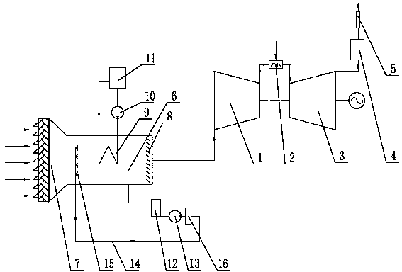
[0017] see image 3 , The present invention includes a compressor 1, the outlet end of the compressor 1 is connected to the inlet end of the combustion chamber 2, the outlet end of the combustion chamber 2 is connected to the inlet end of the gas turbine 3, and the inlet end of the compressor 1 is connected to the air cooler 6 The air outlet pipe is connected, the air inlet of the air cooler 6 is connected with the air outlet of the air filter 7, the air cooler 6 is provided with a demister 8, and the first surface heat exchanger 9 is provided in the air cooler 6, The water inlet of the first surface heat exchanger 9 is connected to the water outlet of the first chilled water circulating pump 10, the water inlet of the first chilled water circulating pump 10 is connected to the chilled water outlet of the main refrigerator 11, and the first surface heat exchanger 9 ...


PUM


Abstract

The invention relates to a combined type energy-saving gas turbine inlet air cooling system which comprises an air compressor, a combustion chamber and a gas turbine, wherein the air compressor is connected with an air outlet pipeline of a cooler, the air inlet of the cooler is connected with an air filter, a demister is arranged in the cooler, a first surface heat exchanger is arranged in the air cooler, the water inlet of the first surface heat exchanger is connected with the water outlet of a first chilled water circulating pump, the water inlet of the first chilled water circulating pump is connected with the chilled water outlet of a main refrigerator, the water outlet of the first surface heat exchanger is connected with the chilled water inlet of the main refrigerator, the water outlet of the cooler is connected with a water inlet of a condensed water tank, condensed water returns to the cooler via a high pressure pipe, an atomizing nozzle is arranged on the high pressure pipe stretching into the cooler, and the high pressure pipe outside the cooler is provided with a condensed water pump and a condensed water filtering device. According to the invention, indirect heat exchange cooling and direct evaporative cooling are adopted by the combination, so that the energy consumption is reduced, the installing capacity of the main refrigerator is reduced, and the system is suitable for use in areas with high temperature and high humidity.

Description

Technical field [0001] The invention relates to a gas turbine inlet air cooling device, in particular to a combination that uses spray direct evaporative cooling and indirect heat exchange cooling, and recovers the condensed water from the indirect heat exchange cooling process and uses it as a cold source for spray direct evaporative cooling A type energy-saving gas turbine intake air cooling system, in particular, relates to a system for cooling the gas turbine intake air used in gas-steam combined cycle power generation. Background technique [0002] In the gas-steam combined cycle power generation system, the main structure of a gas turbine (hereinafter referred to as "gas turbine") includes a compressor, a combustion chamber, and a gas turbine. The compressor compresses the air sucked in, and the compressed air enters the combustion chamber and is injected The fuel mixes and burns into high-temperature gas, which then flows into the gas turbine to expand and do work, pushing...

Claims


Application Information

Patent Timeline
IPC IPC(8): F02C7/141
Inventor 陈若莱夏国华
Owner 无锡金龙石化冶金设备制造有限公司
Learn More