Picosecond pulse laser cutting preparation method for grid-control traveling wave tube grid mesh

A laser cutting and picosecond pulse technology is applied in the field of preparation of traveling wave tube fittings, which can solve the problems of difficulty in guaranteeing the accuracy of the coaxiality of the spoke width, the inconsistency of the electric discharge machining grid, and the unstable quality of the traveling wave tube. , to achieve the effect of narrow processing line width, good edge quality and small heat affected area

Active Publication Date: 2014-01-22
NANJING SANLE GROUP
View PDF5 Cites 52 Cited by
  • Summary
  • Abstract
  • Description
  • Claims
  • Application Information

AI Technical Summary

Problems solved by technology

The grid is an important part of the grid-controlled traveling wave tube, but the processing method of the spherical grid in the prior art is that the machine tool punches a spherical blank and then processes the grid by EDM. The grid prepared by this method is the same as the EDM electrode. Accuracy and clamping have a lot to do with it. There are disadvantages that the coaxiality of each wheel of the spoke grid and the width accuracy of the spokes are difficult to guarantee, and the spoke grid with asymmetrical graphics, the grid with multiple spherical crowns, and the wire diameter are less than 0.05mm The grids are difficult to process, and the consistency of the existing EDM grids is not high, resulting in unstable quality of assembled TWTs

Method used


Image

  • Picosecond pulse laser cutting preparation method for grid-control traveling wave tube grid mesh
  • Picosecond pulse laser cutting preparation method for grid-control traveling wave tube grid mesh
  • Picosecond pulse laser cutting preparation method for grid-control traveling wave tube grid mesh

Examples


Embodiment 1

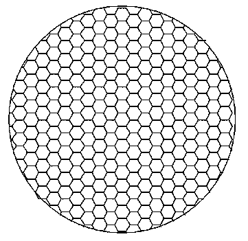
[0024] Example 1 Preparation of Molybdenum Honeycomb Grid

[0025] A preparation method for picosecond pulse laser cutting of a honeycomb grid, which comprises the following steps:

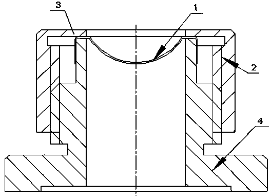
[0026] a. Take the molybdenum grid material with a thickness of 0.03 mm and blank it with a die, clean and remove the oil on the surface of the grid material, then place the grid material in a hydrogen burning furnace, and perform hydrogen annealing treatment at 800 ° C for 15 minutes, then Place the grid material on a convex spherical mold and press it into a spherical round block with a convex center with a punch to obtain a spherical grid blank;

[0027] b. Take the spherical grid blank obtained in step a and clean it with sodium hydroxide solution first, then wash it with chromic acid solution, then place the cleaned spherical grid blank in a hydrogen furnace, and perform hydrogen annealing treatment at 800°C 15 minutes; remove the stress generated during molding to obtain a stress-removed sp...

Embodiment 2

[0030] Example 2 Preparation of grid of oxygen-free copper

[0031] A preparation method for picosecond pulse laser cutting of a honeycomb grid, which comprises the following steps:

[0032] a. After blanking the oxygen-free copper grid material with a thickness of 0.1mm, clean and remove the oil stain on the surface of the grid material, then place the grid material in a hydrogen burning furnace, and perform hydrogen annealing treatment at 650°C for 15 minutes. Then place the grid material on a convex spherical mold and press it into a spherical round block with a convex center with a punch to obtain a spherical grid blank;

[0033] b. Take the spherical grid blank obtained in step a and clean it with sodium hydroxide solution first, then clean it with chromic acid solution, then place the cleaned spherical grid blank in a hydrogen furnace, and anneal it at 650 °C by burning hydrogen Process for 15 minutes; remove the stress generated during molding to obtain a stress-remove...

Embodiment 3

[0036] Example 3 Preparation of Molybdenum-Rhenium Grid

[0037] A preparation method for picosecond pulse laser cutting of a honeycomb grid, which comprises the following steps:

[0038]a. After blanking the molybdenum-rhenium grid material with a thickness of 0.08mm, clean and remove the oil stain on the surface of the grid material, then place the grid material in a hydrogen burning furnace, and anneal hydrogen burning at 900°C for 20 minutes, and then Place the grid material on a convex spherical mold and press it into a spherical round block with a convex center with a punch to obtain a spherical grid blank;

[0039] b. Take the spherical grid blank obtained in step a and clean it with sodium hydroxide solution first, then clean it with chromic acid solution, then place the cleaned spherical grid blank in a hydrogen furnace, and anneal it at 900°C Process for 15 minutes; remove the stress generated during molding to obtain a stress-removed spherical grid blank, for subse...


PUM

PropertyMeasurementUnit
thicknessaaaaaaaaaa
diameteraaaaaaaaaa
diameteraaaaaaaaaa

Abstract

The invention discloses a picosecond pulse laser cutting preparation method for a grid-control traveling wave tube grid mesh. The method comprises the following steps of performing cleaning, hydrogen burning and annealing on a grid mesh material, then pressing the grid mesh material through a die on a punching machine to form a spherical grid mesh blank with high curvature radius precision, performing destressing hydrogen burning on the blank to eliminate stress during processing to guarantee the stability of the curvature radius of a spherical cap of a grid mesh, and finally cutting the grid mesh by adopting picosecond pulse laser of an optimized technology to prepare the grid-control traveling wave tube grid mesh with high size precision and high consistency. According to the preparation method for the grid mesh of a grid-control traveling wave tube, specific technical parameters of picosecond laser cutting are screened through a large number of experiments, the operability is high, the technical design is reasonable, and the application range is large; the prepared grid mesh is high in size precision, high in consistency, high in yield and high in reliability and has an important application value; the shortcoming of an existing electric spark grid mesh processing technology can be effectively overcome.

Description

technical field [0001] The invention relates to a method for preparing traveling wave tube fittings, in particular to a method for preparing grid-controlled traveling wave tube grids by picosecond pulse laser cutting. Background technique [0002] A traveling wave tube is a microwave tube that achieves amplification by modulating the speed of the electron beam. The traveling wave tube is characterized by wide frequency band, high gain, large dynamic range and low noise. The grid is an important part of the grid-controlled traveling wave tube, but the processing method of the spherical grid in the prior art is that the machine tool punches a spherical blank and then processes the grid by EDM. The grid prepared by this method is the same as the EDM electrode. Accuracy and clamping have a lot to do with it. There are disadvantages that the coaxiality of each wheel of the spoke grid and the width accuracy of the spokes are difficult to guarantee, and the spoke grid with asymmetr...

Claims


Application Information

Patent Timeline
Patent Type & Authority Applications(China)
IPC IPC(8): H01J9/14H01J9/16
Inventor 吴亚琴朱军方刘长彪马丽叶杨陆堂邹雯婧
Owner NANJING SANLE GROUP
Why Eureka
Try Eureka