Back contact forming method of passivated emitter and rear contact solar cell

A technology of backside passivation and solar cells, which is applied in circuits, photovoltaic power generation, electrical components, etc., can solve the problems of battery conversion efficiency that cannot be greatly improved, high lithography production costs, and high recombination rate, so as to achieve low production costs and avoid backside damage, reducing recombination rate

Inactive Publication Date: 2014-02-12
中电电气(扬州)光伏有限公司
View PDF0 Cites 4 Cited by
  • Summary
  • Abstract
  • Description
  • Claims
  • Application Information

AI Technical Summary

Problems solved by technology

Generally, the rear passivated solar cells have problems such as high rear recombination rate caused by laser technology or poor rear pattern acc

Method used


Image

  • Back contact forming method of passivated emitter and rear contact solar cell
  • Back contact forming method of passivated emitter and rear contact solar cell

Examples


Embodiment Construction

[0022] The present invention will be further specifically described below through the embodiments and in conjunction with the accompanying drawings.

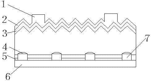
[0023] Firstly, a cell substrate of a first conductivity type for preparing a solar cell is provided. Specifically, the resistivity of p-type single crystal silicon may range from 0.1 ohm·cm to 10 ohm·cm, but is not limited to this range. The front side of the battery substrate is irradiated by sunlight, and the backside of the battery substrate is not irradiated by sunlight when the battery is working.

[0024] Further, a light trapping mechanism is formed on the front side of the battery substrate. Several pyramid-shaped suede surfaces are formed on the front surface of the battery substrate. The textured surface can be formed by anisotropic etching of a chemical solution or mask photolithography, and is usually formed by selective chemical etching. The specific shape of the suede is related to the selected manufacturing pr...


PUM

PropertyMeasurementUnit
Thicknessaaaaaaaaaa

Abstract

The invention discloses a back contact forming method of a passivated emitter and rear contact solar cell. The back contact forming method of the passivated emitter and rear contact solar cell comprises the following steps that (1) a light trapping mechanism is formed on the obverse side of a cell substrate of a first conduction type; (2) doping of a second conduction type is carried out on the obverse side of the cell substrate; (3) an antireflection layer is formed on the obverse side of the cell substrate in a deposition mode; (4) a mask plate is arranged on the top of the back side of the cell substrate; (5) a back passivating dielectric layer is formed on the back side of the cell substrate, and an exposed area, without the passivating dielectric layer, of the back side is formed at the same time; (6) electrode patterns are formed on the back side and the obverse side of the cell substrate respectively, and ohmic contact between electrode metal and silicon is formed in a high-temperature sintering mode. According to the back contact forming method of the passivated emitter and rear contact solar cell, damage caused by laser windowing in the preparation process of the passivated emitter and rear contact solar cell can be eliminated, conversion efficiency of the passivated emitter and rear contact solar cell is improved, the preparation cost of the passivated emitter and rear contact solar cell is reduced, and the risk of the fragmentation rate of module preparation is reduced.

Description

technical field [0001] The invention relates to the preparation of PERC (Passivated emitter and rear contact) solar cell with passivation on the back, and relates to a method for forming the back electrode contact of the PERC solar cell. Background technique [0002] Existing formation of rear passivation solar cell PERC, such as figure 1 As shown, it includes a front electrode 1 , an anti-reflection layer 2 , an emitter 3 , an aluminum-silicon contact 4 , a rear passivation layer 5 , aluminum 6 , and a window area 7 on the rear passivation layer 5 . Generally, after depositing the anti-reflection layer on the front side of the back passivation battery, a passivation layer is deposited on the back side, and the passivation layer uniformly covers the entire area of ​​the back side. Existing methods for forming PERC rear contacts of rear-passivated solar cells generally include laser ablation window opening, chemical mask etching window opening, and photolithography window op...

Claims


Application Information

Patent Timeline
IPC IPC(8): H01L31/18H01L31/0216
CPCH01L31/02167H01L31/022441H01L31/1868Y02E10/50Y02P70/50
Inventor 王玉林
Owner 中电电气(扬州)光伏有限公司
Why Eureka
Try Eureka