A kind of microbubble generator and its manufacturing method and application

A technology of a microbubble generator and a manufacturing method, which is applied in the field of microfluidics, can solve problems such as difficult multiple microbubbles, small heat source area, etc., and achieve low cost and effective, good photothermal characteristics, and good photothermal conversion performance Effect

Active Publication Date: 2016-01-13
SOUTH CHINA NORMAL UNIVERSITY
View PDF0 Cites 0 Cited by
  • Summary
  • Abstract
  • Description
  • Claims
  • Application Information

AI Technical Summary

Problems solved by technology

However, the focused laser beam and the heat source area of ​​the fiber tip are too small to simultaneously generate multiple microbubbles using the above method

Method used


Image

  • A kind of microbubble generator and its manufacturing method and application
  • A kind of microbubble generator and its manufacturing method and application
  • A kind of microbubble generator and its manufacturing method and application

Examples


Embodiment 1

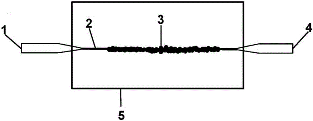
[0043] A microfiber with a diameter of 3.0 μm and a length of 1.2 mm was drawn from a single-mode silica fiber (SMF-28, Corning, USA) by a high-temperature drawing method. Such as figure 1As shown, the micro-optical fiber 2 was immersed in a DMF dispersion of 0.05 mg / mL graphene oxide. Connect the amplified spontaneous emission broadband light source (ASE, 20mW, 1527-1566nm) to the erbium-doped fiber amplifier (EDFA, 1546-1562nm) to obtain an output optical signal with a wavelength of 1527-1566nm and a power of 40mW. The optical signal from the EDFA is input into the optical signal input port 1, and the graphene oxide in the dispersion is adsorbed on the surface of the micro-fiber 2 under the action of the optical gradient force and thermal convection, forming graphene oxide deposits 3, forming a linear heat source. Continue to pass through the light, and the light energy is continuously converted into heat energy, so that the temperature around the graphene oxide deposit 3 ...

Embodiment 2

[0047] A microfiber with a diameter of 1.8 μm and a length of 1.2 mm was drawn from a single-mode silica fiber by a high-temperature drawing method. Such as figure 1 As shown, the micro-optical fiber 2 was immersed in a DMF dispersion of 0.05 mg / mL graphene oxide. Connect the amplified spontaneous emission broadband light source (ASE, 20mW, 1527-1566nm) to the erbium-doped fiber amplifier (EDFA, 1546-1562nm) to obtain an output optical signal with a wavelength of 1527-1566nm and a power of 40mW. The optical signal from the EDFA is input into the optical signal input port 1, and the graphene oxide in the dispersion is adsorbed on the surface of the micro-fiber 2 under the action of the optical gradient force and thermal convection, forming graphene oxide deposits 3, forming a linear heat source. Continue to pass through the light, and the light energy is continuously converted into heat energy, so that the temperature around the graphene oxide deposit 3 continues to rise. Whe...

Embodiment 3

[0049] A microfiber with a diameter of 2.6 μm and a length of 1.5 mm was drawn from a single-mode silica fiber by a high-temperature drawing method. Such as figure 1 As shown, the micro-optical fiber 2 was immersed in a DMF dispersion of 0.05 mg / mL graphene oxide. Connect the amplified spontaneous emission broadband light source (ASE, 20mW, 1527-1566nm) to the erbium-doped fiber amplifier (EDFA, 1546-1562nm) to obtain an output optical signal with a wavelength of 1527-1566nm and a power of 40mW. The optical signal from the EDFA is input into the optical signal input port 1, and the graphene oxide in the dispersion is adsorbed on the surface of the micro-fiber 2 under the action of the optical gradient force and thermal convection, forming graphene oxide deposits 3, forming a linear heat source. Continue to pass through the light, and the light energy is continuously converted into heat energy, so that the temperature around the graphene oxide deposit 3 continues to rise. Whe...


PUM

PropertyMeasurementUnit
Lengthaaaaaaaaaa

Abstract

The invention discloses a micro-bubble generator as well as a manufacturing method and an application thereof. The micro-bubble generator comprises a sample pool, micro optical fiber, photothermal conversion nano material sediment, an optical signal input port and an optical signal output port. The manufacturing method comprises the following steps of putting DMF (Dimethyl Formamide) dispersion fluid of the photothermal conversion nano material into the sample pool; immersing the micro optical fiber into the DMF dispersion fluid of the photothermal conversion nano material in the sample pool; inputting optical signals from the optical signal input port to the micro optical fiber; after the photothermal conversion nano material is absorbed on the surface of the micro optical fiber, forming the photothermal conversion nano material sediment and a linear heat source; further inputting the optical signals, and generating micro-bubbles at the interface between the photothermal conversion nano material sediment and the DMF. The manufacturing method is fast and convenient, is low in cost and is effective. The micro-bubble generator can be used for enriching medium microspheres, cells and biomolecules and the like, and is applicable to the technical fields of sensing, microfluid control, virus detection or biological chips and the like.

Description

technical field [0001] The invention belongs to the field of microfluidic technology, and in particular relates to a microbubble generator and its manufacturing method and application. Background technique [0002] In recent years, microbubble technology has been widely used in various fields (such as medical imaging, biomedical analysis, drug delivery, microfluidic manipulation, etc.). The technique of generating microbubbles in liquids has also attracted increasing attention. At present, a variety of optofluidic systems have been applied to the generation of microbubbles. The researchers found that the light-absorbing substrate [Y.Zheng, etal.LabChip11, 3816(2011)], the light-absorbing particles [Z.Liu, etal. K.Y.Lim, et al.Phys.Rev.E81, 016308 (2010)], can generate microbubbles. Fiber end face coated with nanoparticles [R.Pimentel-Domínguez, etal.Opt.Express20,8732(2012)] and fiber tip [R.Xu, etal.Appl.Phys.Lett.101,054103(2012)] Single microvesicles can also be produ...

Claims


Application Information

Patent Timeline
IPC IPC(8): B01J19/12B01L3/00C12M1/00
Inventor 邢晓波朱德斌郑嘉鹏孙朝孔瑞轩陈伟
Owner SOUTH CHINA NORMAL UNIVERSITY
Why Eureka
Try Eureka