Inclined wide-field optical section scanning imaging microscope system and imaging method thereof

A scanning imaging and microscopic system technology, applied in the field of optical microscopy, can solve the problems of slow scanning speed and so on

Active Publication Date: 2014-04-23
苏州大猫单分子仪器研发有限公司
View PDF8 Cites 34 Cited by
  • Summary
  • Abstract
  • Description
  • Claims
  • Application Information

AI Technical Summary

Problems solved by technology

However, during the scanning process of this kind of optical slice, the scanning process needs to be realized by moving the platform, and the scanning speed is relatively slow.
[0004] However, at present, in many field...

Method used


Image

  • Inclined wide-field optical section scanning imaging microscope system and imaging method thereof
  • Inclined wide-field optical section scanning imaging microscope system and imaging method thereof
  • Inclined wide-field optical section scanning imaging microscope system and imaging method thereof

Examples


Embodiment 1

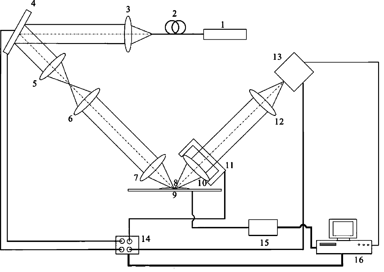
[0050] For an example of imaging a non-fluorescent sample, see figure 1 .

[0051] The imaging display control device is a main control computer 16, a control and imaging display program is installed in the main control computer, through the main control computer 16, a control signal instruction is sent to the data acquisition card, and the imaging device of the present invention is controlled by the data acquisition card. The laser intensity, the deflection angle of the two-dimensional scanning galvanometer, the displacement of the piezoelectric film base, the shutter control of the detector, etc., realize the synchronous action of the two-dimensional scanning galvanometer, the piezoelectric film base, and the shutter control of the detector.

[0052] The main control computer 16 sends a control signal command to the sample stage control device 15 to control the three-dimensional movement of the sample stage.

[0053] The laser emitting device mainly includes a laser 1, a si...

Embodiment 2

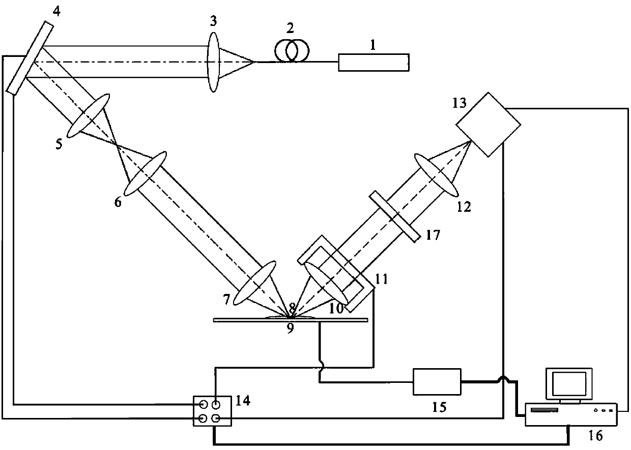
[0061] Take a single-color fluorescent sample labeled with a single-color fluorescent protein as an example.

[0062] The difference from embodiment 1 to the non-fluorescent sample scanning imaging microscope system is that: when scanning and imaging monochromatic fluorescent samples, a filter 17 is installed between the second microscope objective lens 10 and the field lens 12, see figure 2 . The filter 17 allows the fluorescence excited by the scanning laser beam on the fluorescent sample to pass through, eliminates the reflected light and scattered light generated by the scanning laser beam, and only makes the excited fluorescence in the scanning area of ​​the fluorescent sample image on the detection surface of the CCD detector. The structures of other imaging microscope systems are the same as those in Example 1. When laser scanning is performed on fluorescent samples, the emitted laser wavelength is the absorption wavelength corresponding to the fluorescent protein lab...

Embodiment 3

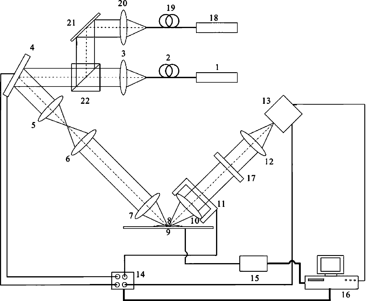
[0064] Take a dual-color fluorescent sample labeled with a dual-color fluorescent protein as an example.

[0065] On the basis of the scanning imaging microscope system for monochromatic fluorescent samples in Example 2, a group of laser emitting devices is added to form two groups of first laser emitting devices and second laser emitting devices arranged in parallel, see image 3 .

[0066] The first laser emitting device comprises laser device 18, single-mode fiber 19, collimating lens 20 and reflector 21 successively, and described second laser generating device comprises laser device 1, single-mode fiber 2, collimating lens 3 and polarization beam splitter successively 22. The laser beam emitted by the laser 18 of the first laser emitting device is coupled by the single-mode optical fiber 19 and then collimated by the collimating lens 20 to form a collimated laser beam, and then reflected by the mirror 21 to the polarization beam splitter 22, and then polarized After bein...


PUM


Abstract

The invention discloses an inclined wide-field optical section scanning imaging microscope system and an imaging method thereof. The inclined wide-field optical section scanning imaging microscope system comprises a laser transmitting device, wherein laser transmitted by the laser transmitting device enters a laser scanning optical path consisting of a two-dimensional scanning galvanometer, a collimator lens group and a first microscope objective to perform inclined scanning on a sample on a sample platform; a second microscope objective, a field lens and a detector form an imaging detection optical path the optical axis of which is perpendicular to the laser scanning optical path; an imaging display control device respectively controls the synchronized action of the two-dimensional scanning galvanometer, the second microscope objective and the detector and the automatic displacement of the sample platform through a data acquisition card and a sample platform control device, and processes acquired imaging data of the detector to form wide field three-dimensional image information of the sample. The imaging microscope system and the imaging method disclosed by the invention have high scanning imaging speed and high resolution and can implement wide field scanning imaging.

Description

technical field [0001] The invention belongs to the field of optical microscopy, in particular to an optical section illumination scanning microscopic imaging device and a microscopic imaging method. Background technique [0002] With the development of science and technology, people have put forward higher and higher requirements for the resolution of microscopic structures and microscopic imaging of biological functions. In addition to the requirement of high resolution, the detection time and detection range also need to be faster and wider. [0003] In 1994, light section illumination fluorescence microscopy, that is, planar light microscopy, was first proposed and used to observe larger samples, initially using orthogonal light section illumination microscopy. In this design, a light section is used to illuminate the sample vertically, and then a fluorescent image of the illuminated surface is observed in a direction perpendicular to the illuminating light. However, d...

Claims


Application Information

Patent Timeline
IPC IPC(8): G01N21/64G02B21/36
Inventor 于冬梅匡翠云毕学卫毕学臣秦培武
Owner 苏州大猫单分子仪器研发有限公司
Why Eureka
Try Eureka