


Quick Research
Generate reliable direction feasibility study reports for your R&D in just a few steps.

Technical Q&A
Discover and master advanced knowledge NOW. Basics, ideas, possibilities, all at once.

Find Solutions
As an expert in R&D theories, this can generate solutions to your technical problems instantly.

Evaluate Feasibility
Analyze your overall solution with one click, know your potential R&D risks in advance.

Monitor Landscape
Get weekly tech updates, stay abreast of the latest tech innovations and key insights.
Method for preparing zirconium carbide ceramic boundary phase on surface of carbon fiber
A zirconium carbide and carbon fiber technology, applied in the directions of carbon fiber, chemical instruments and methods, carbon compounds, etc., can solve the problems of high preparation cost, difficult control, complicated process, etc., and achieve the effect of uniform interface layer thickness and good ablation resistance.
- Summary
- Abstract
- Description
- Claims
- Application Information
AI Technical Summary
Problems solved by technology
Method used
Image

Examples
Embodiment 1
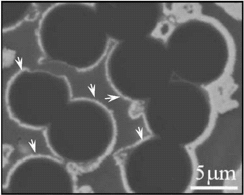
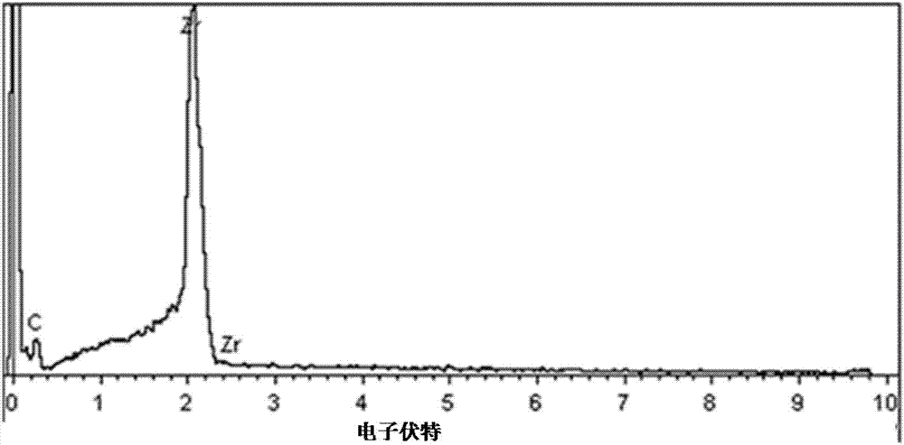
[0024] Weigh 24g of phenolic resin, dissolve it in a mixed solvent of 72g alcohol and butanone to prepare a solution, add 2.28g triolein dropwise, weigh 91.22g of Zr powder, mix it with the above solution for 24 hours by ball milling, and prepare a stable Suspension: put the preform with a fiber content of 26vol% in the suspension, vacuum impregnate for 2 hours, take it out and dry it in vacuum at 80°C for 3 hours; repeat the vacuum impregnation-drying process for 3 times, and place the preform Place it in a graphite crucible and move it to a vacuum carbon tube furnace. Under the condition that the initial vacuum degree in the furnace is 85mtorr, heat it to 1000°C and keep it for 15 minutes to form a ZrC interface phase on the surface of the fiber. The SEM photo of the ZrC interfacial phase prepared by the present embodiment, as figure 1 Shown: the thickness of the interface phase is 70nm (the white ring on the surface of the fiber shown by the arrow in the figure), and the th...
Embodiment 2
[0026] The difference between this example and Example 1 is only that the mass of triolein is 2.01 g, and the mass of Zr powder is 80.27 g.
[0027] The rest of the content is exactly the same as described in Example 1.
[0028] Through detection and analysis, it is found that the thickness of the ZrC interface phase prepared in this example is about 57nm, and the 3D ceramic matrix composite material prepared with the fiber prefabricated body as a reinforcement is evaluated by a plasma wind tunnel experiment with a temperature as high as 2250K. The erosion rate is 0.0023g / s.
Embodiment 3
[0030] The difference between this example and Example 1 is only that the mass of triolein added dropwise is 2.33 g, and the mass of Zr powder is 93.04 g.
[0031] The rest of the content is exactly the same as described in Example 1.
[0032] Through detection and analysis, it is known that the thickness of the ZrC interface phase prepared in this example is about 85nm, and the 3D ceramic matrix composite material prepared with the fiber prefabricated body as a reinforcement is evaluated by a plasma wind tunnel experiment with a temperature as high as 2250K. The erosion rate is 0.0015g / s.
PUM
| Property | Measurement | Unit |
|---|---|---|
| Thickness | aaaaa | aaaaa |
| Mass ablation rate | aaaaa | aaaaa |
| Thickness | aaaaa | aaaaa |
Abstract
Description
Claims
Application Information
 - R&D Engineer
- R&D Manager
- IP Professional
- Industry Leading Data Capabilities
- Powerful AI technology
- Patent DNA Extraction
Browse by: Latest US Patents, China's latest patents, Technical Efficacy Thesaurus, Application Domain, Technology Topic, Popular Technical Reports.
© 2024 PatSnap. All rights reserved.Legal|Privacy policy|Modern Slavery Act Transparency Statement|Sitemap|About US| Contact US: help@patsnap.com