
Fixed supporting beam vibration electromagnetic self-powered microsensor in radio frequency receiving and transmitting assembly of Internet of Things

A radio frequency transceiver and micro-sensor technology, applied in piezoelectric devices/electrostrictive devices, electromagnetic wave systems, generators/motors, etc., can solve problems such as impermissibility, limited energy supply life, large size and weight, etc., and achieve suppression Effects of dithering, improved electromagnetic compatibility, size and weight reduction

Inactive Publication Date: 2014-05-28
SOUTHEAST UNIV
View PDF4 Cites 6 Cited by
  • Summary
  • Abstract
  • Description
  • Claims
  • Application Information

AI Technical Summary

Problems solved by technology

There are obvious defects in traditional batteries: First, its size and weight are still too large compared to micro-sensor devices, which limits the further miniaturization of micro-sensors; second, the energy supply life is limited, and batteries need to be replaced or charged after a period of use. Under normal circumstances, it is not allowed to replace the battery in the device structure and system; the third is that the use of a large number of batteries will cause harm to the environment

Method used


Image

  • Fixed supporting beam vibration electromagnetic self-powered microsensor in radio frequency receiving and transmitting assembly of Internet of Things
  • Fixed supporting beam vibration electromagnetic self-powered microsensor in radio frequency receiving and transmitting assembly of Internet of Things
  • Fixed supporting beam vibration electromagnetic self-powered microsensor in radio frequency receiving and transmitting assembly of Internet of Things

Examples


Embodiment Construction

[0015] The specific implementation scheme of the fixed-support beam vibration / electromagnetic self-powered microsensor in the radio frequency transceiver component of the Internet of Things of the present invention is as follows:

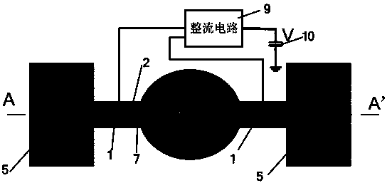
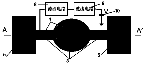
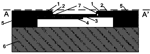
[0016] On the gallium arsenide substrate 6 is provided: a MEMS fixed support beam, and a filtering circuit 8 , a rectification circuit 9 and an energy storage capacitor 10 are supplemented on the periphery of the fixed support beam.

[0017] The MEMS fixed support beam consists of five layers, from top to bottom: upper electrode 1, piezoelectric film 2, lower electrode 7, silicon nitride dielectric layer 3 and rectangular microstrip patch antenna 4. The fixed support beam structure is wide in the middle and narrow in both sides. The fixed beam is used to integrate two kinds of energy harvesting modules, the piezoelectric transducer and the rectenna system. The material used for the upper electrode 1 and the lower electrode 7 is Au.

[0018] The pi...


PUM


Abstract

The invention discloses a fixed supporting beam vibration electromagnetic self-powered microsensor in a radio frequency receiving and transmitting assembly of the Internet of Things. The two energy collecting self-powered modules of a piezoelectric transducer and a rectifying antenna system are integrated, and the functions of collection, conversion and energy storage can be respectively achieved on mechanical vibrational energy and stray electromagnetic energy. Gallium arsenide is used as a substrate, and the microsensor is composed of an MEMS fixed supporting beam, a filter circuit, a rectifying circuit and an energy storage capacitor. Fiver layers of an upper electrode, a piezoelectric film, a lower electrode, a silicon nitride dielectric layer and a rectangular microstrip patch antenna are arranged on the MEMS fixed supporting beam from top to bottom. Integration of the two modules can complement each other, the microstrip antenna structure is used as inertia force and deformation of mass block reinforcing beam vibration, and the directivity range of energy collecting by the microstrip patch antenna can be widened along with vibration of the beam. Energy collecting efficiency and power supply capacity are improved, the effective scheme is provided for solving the self-powered problem of a low-power-consumption system, the electromagnetic compatibility performance of the system is enhanced, and the shake of the system structure is reduced.

Description

technical field [0001] The invention proposes a fixed-support beam vibration / electromagnetic self-powered microsensor in a radio frequency transceiver component of the Internet of Things, which belongs to the technical field of microelectromechanical systems. Background technique [0002] With the continuous progress and development of micro-intelligent systems such as the Internet of Things, micro-mechanical systems (MEMS) and wireless sensor networks, the requirements for miniaturization, self-power supply, and low power consumption are getting higher and higher. The energy harvesting self-powered sensor technology emerging in recent years provides an effective solution to the above problems. Thanks to the advancement of micro-power integrated circuit technology and microelectromechanical systems (MEMS), miniature energy-harvesting self-powered sensing technology has become an important research field and is developing rapidly, attracting more and more people's attention. ...

Claims


Application Information

Patent Timeline
IPC IPC(8): H02N2/18H02J17/00B81B3/00B81C1/00H02J50/20H02J50/27
Inventor 廖小平王文岩
Owner SOUTHEAST UNIV
Learn More