The structure and application of a heat protection coating for rocket launch pad

A technology for rocket launch and thermal protection, applied in coatings, fire protection, building components, etc., can solve the problems of heavy weight, thick thickness, and inability to move the launch platform, and achieve the effect of reducing thermal ablation and thermal shock

Active Publication Date: 2016-08-03
DALIAN INST OF CHEM PHYSICS CHINESE ACAD OF SCI +1
View PDF5 Cites 0 Cited by
  • Summary
  • Abstract
  • Description
  • Claims
  • Application Information

AI Technical Summary

Problems solved by technology

In foreign countries, the Ariane rocket launch platform of the European Space Agency in Guyana, South America is a concrete launch platform. This type of launch platform constructed of inorganic non-metallic materials has better gas purging and ablation resistance than organic ablation coatings, but the disadvantage is that it is thick. , heavy, and the launch pad cannot be moved
[0003] The rocket launch pad can be thermally protected by using special thermal protection coating materials and structures, but at present, there are no relevant reports on the technology of thermal protection for the launch pad

Method used


Image

  • The structure and application of a heat protection coating for rocket launch pad
  • The structure and application of a heat protection coating for rocket launch pad
  • The structure and application of a heat protection coating for rocket launch pad

Examples


Embodiment 1

[0019] The preparation of embodiment 1 thermal protective coating structure

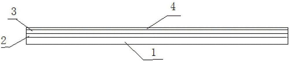
[0020] 1. Preparation of organic bottom layer: mix epoxy resin SM828, curing agent polyamide 650, and toughening agent liquid rubber in a ratio of 7:2:1, and then coat it on the 190×120×5mm surface after removing rust and paint. On the steel plate, the coating thickness is 2mm.

[0021] 2. Preparation of the middle layer: Clay refractory bricks (NZ)-2 with a thickness of 5 mm were pasted on the organic bottom layer.

[0022] 3. Preparation of organic-inorganic composite surface layer: First, mix the filler sand and cement evenly in a ratio of 2:1, and then add it to the mixed glue of organic adhesive epoxy resin SM815 and polyurethane curing agent 735 in a ratio of 3:1, solid The ratio to liquid is 3:1. Coat the surface layer material on the refractory brick with a coating thickness of 3mm to prepare a thermal protective coating with a total thickness of 10mm.

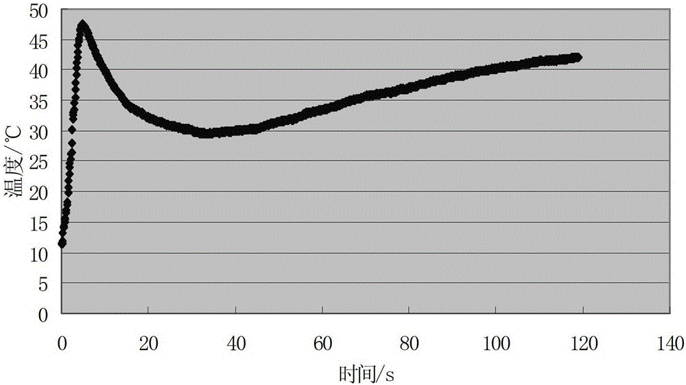
[0023] Tests on the thermal protect...

Embodiment 2

[0025] The preparation of embodiment 2 thermal protection coating structure

[0026] 1. Preparation of organic bottom layer: mix epoxy resin SM828, curing agent polyamide 650, and toughening agent liquid rubber in a ratio of 7:2:1, and then coat it on the 190×120×5mm surface after removing rust and paint. On the steel plate, the coating thickness is 4mm.

[0027] 2. Preparation of the middle layer: Paste the clay refractory brick (NZ)-2 with a thickness of 15mm on the organic bottom layer.

[0028] 3. Preparation of organic-inorganic composite surface layer: First, mix the filler sand and cement evenly in a ratio of 2:1, and then add it to the mixed glue of organic adhesive epoxy resin SM815 and polyurethane curing agent 735 in a ratio of 3:1, solid The ratio to liquid is 3:1. Coat the surface layer material on the refractory brick with a coating thickness of 6mm to prepare a thermal protective coating with a total thickness of 15mm.

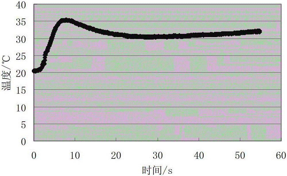
[0029] Tests on the thermal protection...


PUM

PropertyMeasurementUnit
flame retardantaaaaaaaaaa
thicknessaaaaaaaaaa
thicknessaaaaaaaaaa

Abstract

The invention discloses a structure for a thermal protective coating of a rocket launching pad and an application thereof. The thermal protective coating is composed of materials in three layers, namely, an organic bottom layer, refractory bricks and an organic-inorganic compound surface layer, wherein the organic bottom layer is composed of epoxy resin, solidifying agent polyamide and flexibilizer liquid rubber; clay refractory bricks are adopted as the refractory bricks; the organic-inorganic compound surface layer is composed of organic rubber epoxy resin, polyurethane curing agent, sand and cement. The material of the thermal protective coating provided by the invention can endure the scouring of the simulated fuel gas flow of a rocket; the temperature on a metal rear surface is not above 200 DEG C; the coating has an excellent heat-insulating property.

Description

technical field [0001] The invention relates to a heat protection coating structure of a rocket launch pad, in particular to a heat protection coating structure for coating the surface of a rocket launch pad to reduce the back temperature of the launch pad and an application thereof, which belongs to the field of high temperature resistance and heat insulation protection. Background technique [0002] With the development of aerospace and aerospace industry, thermal protective coatings have opened up new application fields. In addition to the thermal protection of the aircraft itself, thermal protection measures have also been added to ground facilities such as rocket launch pads in China. If the launch pad is coated with thermal protective coatings, it can insulate the metal surface, reduce thermal ablation and thermal shock, and prevent the launch pad from thermal fatigue, thermal cracking and thermal fracture under multiple thermal shock loads, thereby ensuring The relia...

Claims


Application Information

Patent Timeline
Patent Type & Authority Patents(China)
IPC IPC(8): E04B1/94E04B1/78C09D163/00C09D7/12
CPCY02A30/244
Inventor 马磊张巍臧红王国鹏张涛徐铮罗强贾永涛吴梦强刘聪聪何冠杰张锐
Owner DALIAN INST OF CHEM PHYSICS CHINESE ACAD OF SCI
Why Eureka
Try Eureka