Carbon nanotube composite thin film field emission cathode preparation method

A carbon nanotube composite, field emission cathode technology, applied in cold cathode manufacturing, discharge tube/lamp manufacturing, nanotechnology and other directions, can solve the problems of limiting field emission performance, limiting emission current, small contact area, etc. The effect of improving field emission performance, reducing ohmic contact resistance and increasing contact area

Active Publication Date: 2014-06-18
SHENZHEN INST OF ADVANCED TECH CHINESE ACAD OF SCI
View PDF4 Cites 13 Cited by
  • Summary
  • Abstract
  • Description
  • Claims
  • Application Information

AI Technical Summary

Problems solved by technology

However, these methods limit the further improvement of field emission performance due to the poor wettability between the surface of carbon nanotubes and most metal surfaces, and the formation of Schottky barriers rather than ohmic contacts between carbon nanotubes and metals.
The high-temperature vacuum annealing method uses Ti as the electrode of carbon nanotubes to form a TiC interlayer at high temperature, thereby forming an ohmic contact between carbon nanotubes and metals. However, this method requires high temperatures above 800°C, and the substrate material Puts high demands, is not suitable for most low temperature applications, and the contact area formed by this method is small, which also limits the current emitted

Method used


Image

  • Carbon nanotube composite thin film field emission cathode preparation method
  • Carbon nanotube composite thin film field emission cathode preparation method
  • Carbon nanotube composite thin film field emission cathode preparation method

Examples


Embodiment Construction

[0022] The present invention will be further described in detail below in conjunction with the accompanying drawings and specific embodiments.

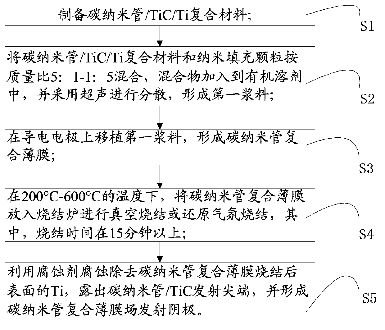
[0023] Please refer to figure 1 , the invention provides a method for preparing a carbon nanotube composite film field emission cathode, the method comprising:

[0024] S1, preparing carbon nanotube / TiC / Ti composite material;

[0025] In said S1, the specific method for preparing carbon nanotubes / TiC / Ti composite materials is as follows: carbon nanotubes, TiCl 3 and TiH 2 Put the uniform mixed powder into the sealed cavity, vacuumize the sealed cavity and heat it for 10 minutes to 2 hours. After the mixed powder volatilizes and undergoes a chemical reaction for 1 hour, reduce the temperature of the sealed cavity to room temperature to obtain the reaction product. The solvent cleans the reaction product to obtain the carbon nanotube / TiC / Ti composite material. Among them, the vacuum degree is 10 -2 Below Pa, the heating temperature...


PUM

PropertyMeasurementUnit
lengthaaaaaaaaaa
diameteraaaaaaaaaa
particle diameteraaaaaaaaaa

Abstract

The invention provides a carbon nanotube composite thin film field emission cathode preparation method. The carbon nanotube composite thin film field emission cathode preparation method includes the following steps that: S1, nanotube/TiC/Ti composite materials are prepared; S2, the nanotube/TiC/Ti composite materials and nano filling particles are mixed according to at the mass ratio of 5:1 to 1:5, and the mixture is added to an organic solvent, and ultrasound is adopted to perform dispersion, and a first slurry can be formed; S3, the first slurry is transplanted on a silver electrode, and a nanotube composite film can be formed; S4, the nanotube composite film is put into a sintering furnace so as to be subjected to vacuum sintering or reducing atmosphere sintering for more than 15 minutes under temperature from 200 DEG C to 600 DEG C; S5, Ti on the surface of the sintered carbon nanotube composite film is corroded and removed through using a corrodent, and a carbon nanotube/TiC emission tip is exposed, and a carbon nanotube composite thin film field emission cathode can be formed. With the carbon nanotube composite thin film field emission cathode prepared by the invention adopted, adhesion and electrical contact between the emitter and the base of a carbon nanotube can be improved, and field emission performance can be improved.

Description

technical field [0001] The invention relates to the field of carbon nanotube field emission cathode preparation field, in particular to a preparation method of carbon nanotube composite film field emission cathode. Background technique [0002] Carbon nanotubes have a quasi-one-dimensional structure with a high aspect ratio, excellent mechanical properties and chemical stability, and are ideal materials for field emission cathodes instead of silicon tips, tungsten tips, and molybdenum tips. However, due to the poor wettability and weak binding force between the surface of carbon nanotubes and substrates such as metals or resins, the adhesion of the carbon nanotube thin film cathode to the substrate is small and the contact resistance is large, thereby increasing the entire electron emission circuit. heat dissipation, and instability of electron emission. These shortcomings inhibit the superior field emission performance of carbon nanotubes, and affect the application prospe...

Claims


Application Information

Patent Timeline
Patent Type & Authority Applications(China)
IPC IPC(8): H01J9/02B82Y30/00
Inventor 陈婷洪序达陈垚孙竹桂建保郑海荣
Owner SHENZHEN INST OF ADVANCED TECH CHINESE ACAD OF SCI
Why Eureka
Try Eureka