A matching welding rod for low temperature steel containing ni

A low-temperature steel and welding rod technology, applied in welding equipment, welding media, welding/cutting media/materials, etc., can solve the problems of low-temperature impact toughness reduction, pro-eutectoid ferrite increase, and inclusions that cannot be effectively controlled , to achieve the effects of improving low temperature impact toughness, good crystal matching, and improving the shape of inclusions

Active Publication Date: 2016-03-16
JIANGSU JIUZHOU NEW MATERIAL TECH CO LTD
View PDF7 Cites 0 Cited by
  • Summary
  • Abstract
  • Description
  • Claims
  • Application Information

AI Technical Summary

Problems solved by technology

However, the electrodes matched with 3.5Ni in the prior art often have the following disadvantages: when the welding current is too large or the energy of the vertical welding line is large, it is easy to cause the increase of proeutectoid ferrite and the coarsening of grains in the weld metal. This leads to the adverse consequences of decreased toughness; the sulfur content of the weld metal is large, and the inclusions cannot be effectively controlled, resulting in a decrease in low-temperature impact toughness; the coating has poor moisture absorption resistance; the coating is not easy to remove slag

Method used


Image

  • A matching welding rod for low temperature steel containing ni
  • A matching welding rod for low temperature steel containing ni
  • A matching welding rod for low temperature steel containing ni

Examples


Embodiment 1

[0026] Embodiment 1: the percentage by weight of each component in the drug skin is shown in the following table:

[0027] Raw material name

weight percentage

Raw material name

weight percentage

marble

40

manganese metal

4.5

Fluorite

25

Atomized ferrosilicon

5

barium carbonate

5

Rare earth ferrosilicon

2

Silica powder

2

ferro-titanium

4

lithium carbonate

0.5

Aluminum-magnesium alloy

0.5

Rare earth fluoride

1

nickel powder

9

Borax

0.5

sodium alginate

1

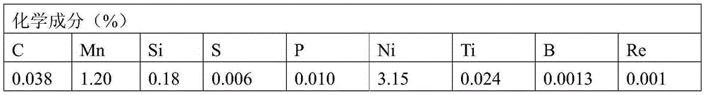
[0028] The deposited metal composition of the electrode prepared according to the above ratio is shown in the following table:

[0029]

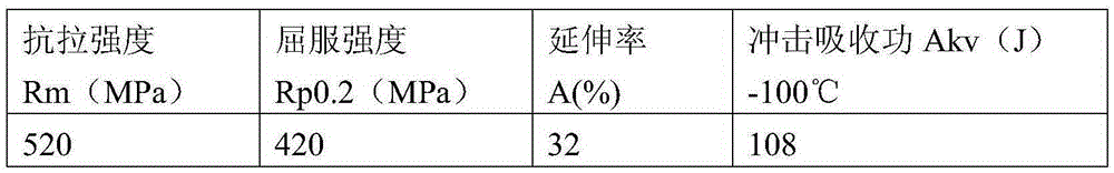
[0030] The mechanical properties of the deposited metal of the electrode prepared according to the above ratio are shown in the following table:

[0031]

[0032] The hydrogen content of the deposited metal in the electrode pre...

Embodiment 2

[0034] Embodiment 2: the percentage by weight of each component in the drug skin is shown in the following table:

[0035] Raw material name

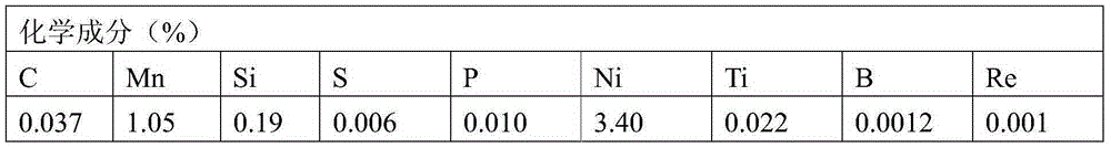
[0036] The deposited metal composition of the electrode prepared according to the above ratio is shown in the following table:

[0037]

[0038]The mechanical properties of the deposited metal of the electrode prepared according to the above ratio are shown in the following table:

[0039]

[0040] The hydrogen content of the deposited metal of the electrode prepared according to the above ratio (mercury method ml / 100g) is shown in the following table:

[0041] sample

[0042] content

Embodiment 3

[0043] Embodiment 3: the percentage by weight of each component in the drug skin is shown in the following table:

[0044] Raw material name

weight percentage

Raw material name

weight percentage

marble

44

manganese metal

2

Fluorite

21

Atomized ferrosilicon

3.6

barium carbonate

3.5

Rare earth ferrosilicon

3

Silica powder

3.5

ferro-titanium

4.5

lithium carbonate

0.7

Aluminum-magnesium alloy

0.7

Rare earth fluoride

1

nickel powder

11

Borax

0.8

sodium alginate

0.7

[0045] The deposited metal composition of the electrode prepared according to the above ratio is shown in the following table:

[0046]

[0047] The mechanical properties of the deposited metal of the electrode prepared according to the above ratio are shown in the following table:

[0048]

[0049] The hydrogen content of the deposited metal of the elec...


PUM

PropertyMeasurementUnit
thicknessaaaaaaaaaa
thicknessaaaaaaaaaa
decomposition temperatureaaaaaaaaaa

Abstract

The invention provides a welding rod containing low temperature steel containing Ni. A coating of the welding rod at least comprises, by mass, 40-50% of marble, 18-25% of fluorite, 2-5% of barium carbonate, 2-5% of silica powder, 0.5-1.0% of lithium carbonate, 0.5-1.0% of rare earth fluoride, 0.5-1.0% of borax, 2-5% of manganese metal, 2-5% of atomized silicon iron, 2-4% of rare earth silicon iron, 3-6% of ferrotitanium, 0.5-1.0% of aluminum magnesium alloy, 9-11% of nickel powder and 0.4-1.0% of sodium alga acid. Sodium potassium silicate is added into the coating of the welding rod formed by mixing the components according to the ratio, an H04E welding core is coated with the coating through a welding rod coating machine, an electric welding rod is dried by a drier and set, the deposited metal diffusible hydrogen content of the electric welding rod is effectively controlled, the deposited metal diffusible hydrogen content is 3.5ml / 100g, and the standard requirement for an ultralow hydrogen welding rod is met.

Description

technical field [0001] The invention relates to a welding rod matched with Ni-containing low-temperature steel, which belongs to the field of welding materials. Background technique [0002] The 3.5Ni low-temperature pressure vessel steel (ASME grade SA203E) used at -100°C is a commonly used steel in foreign countries. The United States, Japan and Germany have already used it for -80°C and -101°C vessels. China used to rely entirely on imports of this steel . Only in 1978, combined with the ethylene project with an annual output of 115,000 tons, a semi-industrial test of 3.5Ni steel was carried out by Taiyuan Iron and Steel Company. In 1984, in the "coal gasification project" project of the national major technical equipment scientific and technological breakthrough, the low-temperature 3.5Ni steel application project was determined. In 1986, the localization of 3.5Ni steel was included in the "Seventh Five-Year Plan" research project of the Ministry of Metallurgy. The 3.5...

Claims


Application Information

Patent Timeline
Patent Type & Authority Patents(China)
IPC IPC(8): B23K35/365
CPCB23K35/0266B23K35/3066B23K35/3602B23K35/404
Inventor 余细华孔健
Owner JIANGSU JIUZHOU NEW MATERIAL TECH CO LTD
Why Eureka
Try Eureka