AlGaN/GaN HEMT manufacturing method

A technology with high electron mobility and manufacturing methods, which is applied in semiconductor/solid-state device manufacturing, circuits, electrical components, etc., can solve problems such as the inability to obtain thin lines and the decrease in lithography resolution, and achieve improved microwave performance and morphology good effect

Inactive Publication Date: 2014-07-16
NO 55 INST CHINA ELECTRONIC SCI & TECHNOLOGYGROUP CO LTD
View PDF6 Cites 14 Cited by
  • Summary
  • Abstract
  • Description
  • Claims
  • Application Information

AI Technical Summary

Problems solved by technology

Because the ions in the ion implantation process have higher energy, the thicker the photoresist mask layer is, the better the protective effect is. The problem brought by the thicker photoresist layer is that the resolution of photolithography decreases, and it is impossible to obtain higher thin lines

Method used


Image

  • AlGaN/GaN HEMT manufacturing method
  • AlGaN/GaN HEMT manufacturing method
  • AlGaN/GaN HEMT manufacturing method

Examples


Embodiment 1

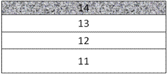
[0047] Such as Figure 2A As shown, a dielectric layer 14 is deposited on the AlGaN barrier layer 13, and the optional materials for the dielectric layer 14 include but are not limited to SiN, SiO 2 etc., preferably SiN, with a preferred thickness of 50 nm.

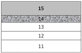
[0048] Such as Figure 2B A photoresist layer 15 is shown coated on the dielectric layer 14 . By exposing and developing the photoresist layer 15, the photoresist layer 15 above the area that needs to be protected by a mask during the ion implantation process, such as Figure 2C The metal layer 16 used as an implant mask is shown evaporated onto the dielectric layer 14 from which the photoresist layer 15 has been removed and on the surface of the photoresist layer 15 .

[0049] Such as Figure 2D As shown, the metal layer 16 can be made of a metal such as Ti, Pt, Ni, Au, etc., or can be made of an alloy of these metals, and their multi-layer composite metal layers, and its thickness depends on the Si that needs to be ...

Embodiment 2

[0062] Depend on Figure 3A-Figure 3G It is the implementation steps of another embodiment of the present invention, at first with embodiment 1 Figures 2A-2F As shown, the deposition of the dielectric layer 14, the coating of the photoresist layer 15 on the dielectric layer 14, the exposure and development to remove the photoresist layer 15 above the area that requires a mask to be protected during the ion implantation process, and evaporation as implantation The metal layer 16 used for the mask is removed on the dielectric layer 14 of the photoresist layer 15 and the surface of the photoresist layer 15, stripping and removing the photoresist layer 15 and the metal layer 16 on it, utilizing the remaining metal layer 16 is used as a mask to implant Si+ ions into the region to be ion-implanted to form an implanted region 17, remove the dielectric layer 14 and the metal mask layer 16 thereon, deposit the dielectric layer 18 to the surface of the AlGaN barrier layer 13, and Medi...


PUM

PropertyMeasurementUnit
thicknessaaaaaaaaaa
thicknessaaaaaaaaaa
thicknessaaaaaaaaaa

Abstract

The invention discloses an AlGaN / GaN HEMT manufacturing method. The method comprises the steps that (1) a first dielectric layer is deposited on an AlGaN barrier layer; (2) the first dielectric layer is coated with a first photoresist layer; (3) a metal mask layer used as an injection mask is evaporated until the metal mask layer is removed from the first dielectric layer of the first photoresist layer and removed from the surface of the first photoresist layer, and a metal layer left by the metal mask layer on the first photoresist layer is stripped and removed; (4) the metal mask layer is used as the mask to inject Si+ ions into an area where ions need to be injected to form an injection area; (5) after the first dielectric layer and the metal mask layer on the first dielectric layer are removed, a second dielectric layer is deposited on the surface of the AlGaN barrier layer, and high temperature annealing is conducted in protective gas to activate the injected Si+ ions to form a dopant. The AlGaN / GaN HEMT manufacturing method has the advantages that the appearance of the surface and the edge of an ohmic contact electrode of a manufactured device is good, the effective source-drain interval of the device is reduced through heavy doping, and therefore the microwave performance of the device is improved.

Description

technical field [0001] The invention relates to a method for manufacturing an aluminum gallium nitride compound / gallium nitride high electron mobility transistor, belonging to the technical field of semiconductor manufacturing. Background technique [0002] Aluminum Gallium Nitride (AlGaN) / Gallium Nitride (GaN) High Electron Mobility Transistor (HEMT), as the third-generation wide bandgap compound semiconductor device, has the characteristics of high output power, high operating frequency, and high temperature resistance, and is suitable for millimeter waves and below The high-power applications in various frequency bands make it a hot spot in the research of semiconductor microwave power devices in recent years. In terms of output power, the output power density of the currently disclosed small-size AlGaN / GaN HEMTs can reach above 30W / mm (Wu et al. IEEE Electron Device Lett., Vol.25, No.3, pp.117-119, 2004. ), the single-chip continuous wave output power of large-scale dev...

Claims


Application Information

Patent Timeline
Patent Type & Authority Applications(China)
IPC IPC(8): H01L21/335H01L21/265
CPCH01L29/66462H01L21/26546
Inventor 任春江孙高峰陈堂胜
Owner NO 55 INST CHINA ELECTRONIC SCI & TECHNOLOGYGROUP CO LTD
Why Eureka
Try Eureka